Novel cooling water tower
A cooling water tower, a new type of technology, used in water shower coolers, heat exchanger types, direct contact heat exchangers, etc., can solve the problems of short life and low heat exchange efficiency, and achieve reasonable structure and low drift rate. , the effect of less water consumption
- Summary
- Abstract
- Description
- Claims
- Application Information
AI Technical Summary
Problems solved by technology
Method used
Image

Examples
Embodiment 1
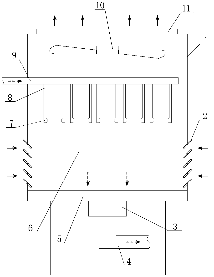
[0027] refer to Figure 1 to Figure 4 , the present invention includes a water tower housing 1 with a cooling chamber 6 inside; the top of the water tower housing 1 is provided with an exhaust hole 11, and an exhaust fan 10 is provided at the exhaust hole 11;
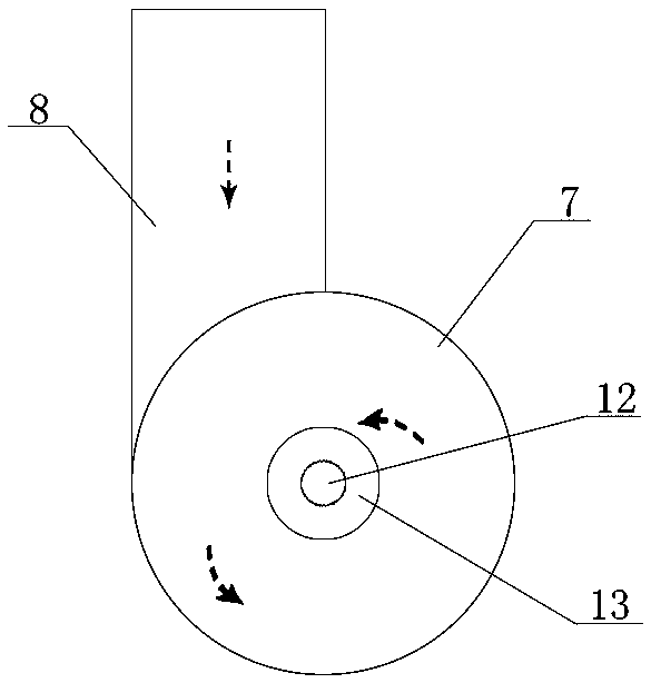
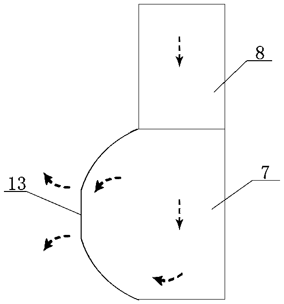
[0028] The upper part of the water tower housing 1 is provided with a water inlet pipe 9, and the water inlet pipe 9 communicates with the shower head 7 through several branch pipes 8; the axis of the shower head 7 and the axis of the branch pipe 8 are longitudinally corresponding to each other, And the branch pipe 8 and the shower head 7 communicate with each other in a circumscribed angle; the shower head 7 is cylindrical as a whole, and one end of the shower head 7 is provided with a horizontal spray hole 13; One end of the shower head 7 is tapered, and the diameter of the tapered nozzle gradually shrinks toward the horizontal spray hole 13; the shower heads 7 are in groups of two, and the horizontal spray nozzles of...
Embodiment 2
[0047] A shower head, which is prepared according to the following process:
[0048] Take 100kg of aluminum powder, 30kg of aluminum-nickel master alloy, 10kg of aluminum-copper master alloy, and 10kg of aluminum-scandium master alloy; put them into the electric melting furnace in turn, raise the temperature, control the melting temperature to 800°C, and melt the prepared melt for 2 hours Take it out, pour it into the mold, cool to 600°C at a cooling rate of 20°C / s, hold for 120s, then cool to 400°C at a rate of 10°C / s, hold for 180s, and then cool at a rate of 10°C / s to room temperature, demoulding to obtain the blank; heating the blank to 400°C at a heating rate of 5°C / s, keeping it warm for 30 minutes, then cooling down to room temperature; then raising the temperature to 500°C at a heating rate of 10°C / s, keeping it warm for 60 minutes, and then Cool down to room temperature; remove burrs; the aluminum-nickel master alloy is AlNi10; the aluminum-copper master alloy is AlCu...
Embodiment 3
[0050] The performance test of shower head material of the present invention:
[0051] Set up a control group, control group 1: do not add aluminum-nickel master alloy, and the rest are the same as in Example 2; control group 2: do not add aluminum-copper master alloy, and the rest are the same as in Example 2; With embodiment 2; The performance parameters of each group are shown in Table 1:
[0052] Table 1
[0053] group
[0054] As shown in Table 1, the present invention improves the mechanical properties, corrosion resistance and high temperature resistance of the alloy material by adding nickel, copper and scandium elements, and greatly prolongs the service life.
PUM
 Abstract
Description
Claims
Application Information
 - R&D
- Intellectual Property
- Life Sciences
- Materials
- Tech Scout
- Unparalleled Data Quality
- Higher Quality Content
- 60% Fewer Hallucinations
Browse by: Latest US Patents, China's latest patents, Technical Efficacy Thesaurus, Application Domain, Technology Topic, Popular Technical Reports.
© 2025 PatSnap. All rights reserved.Legal|Privacy policy|Modern Slavery Act Transparency Statement|Sitemap|About US| Contact US: help@patsnap.com