
Connecting piece and connecting arrangement

Inactive Publication Date: 2005-04-05
FRANZ VIEGENER II GMBH & CO KG
View PDF68 Cites 41 Cited by
  • Summary
  • Abstract
  • Description
  • Claims
  • Application Information

AI Technical Summary

Benefits of technology

In the prior art, supporting pipes constructed as a connecting piece were suggested, which supporting pipes are pushed into a pipe for establishing a pressed connection. For this purpose, the supporting pipe has a stub whose outer circumference corresponds approximately to the inner circumference of the pipe. For establishing a pressed connection, a pressure sleeve is placed around an end section of the stub and this pressure sleeve is then pressed onto the pipe so that the pipe made of a plastic or a composite material is durably held against the supporting pipe in a pressed manner in order to obtain a secure sealing. Such supporting pipes and connecting arrangements have the disadvantage that, after the sliding-in of the stub of the supporting pipe, a preliminary sealing between the pipe and the stub can be obtained so that a preliminary sealing is achieved even without a pressed connection. However, after a short time, an unintentional leakage may result. This effect is intensified when a receiving device for a sealing ring is arranged on the stub. The sealing ring, after the sliding-in, then provides a sealing with the pipe.
According to a preferred embodiment, adjacent to the spacer, the stub has a section which can be pressed together and has an essentially ring-shaped cross-section. Thus, when known pressing tools with round cheek plates are used, a uniform contact pressure is obtained in the area of the pressed section. The uniform pressure on the stub permits a minimizing of the stressing of the material on the pipe and the stub.
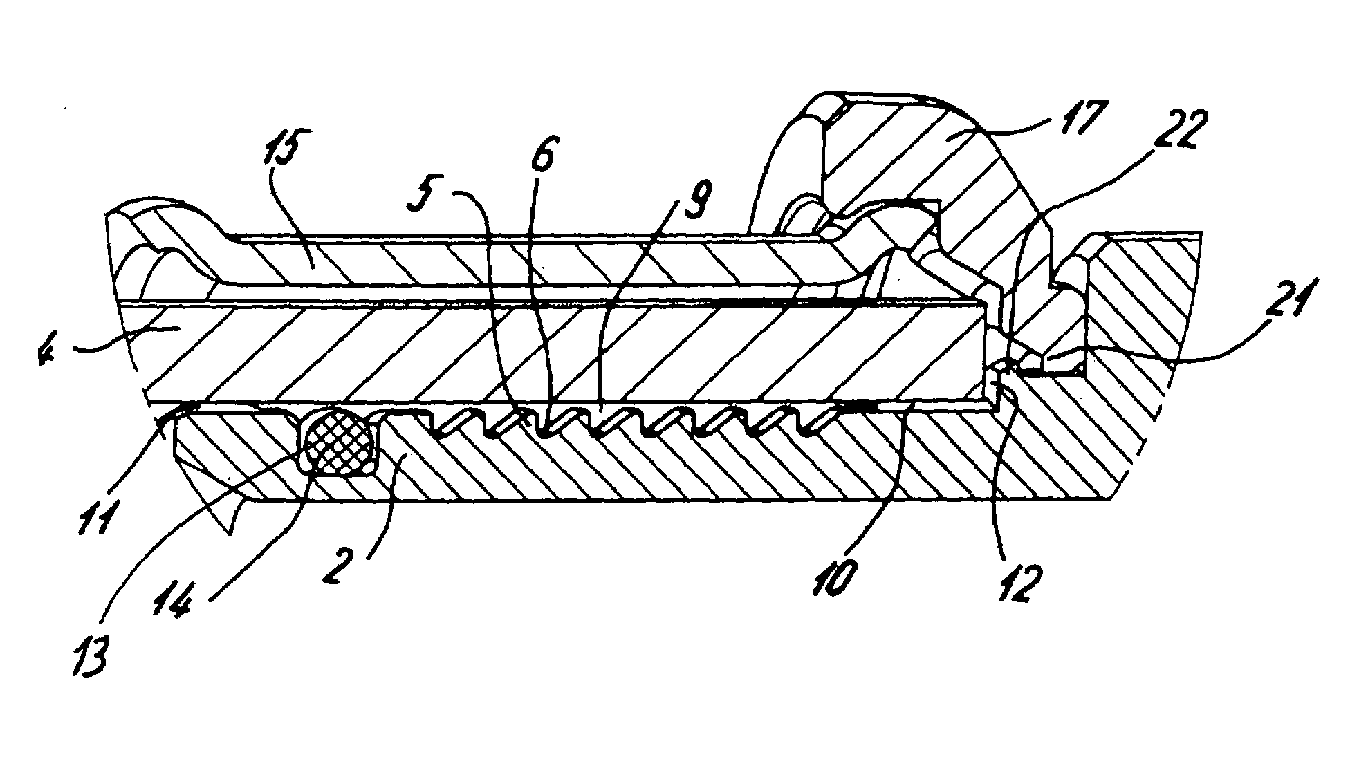
In order to obtain a durable pressed connection secured against displacements, a pressable section is preferably provided on the stub. The section has a plurality of ribs which are circular on the outer circumference. As a result, the material of the pipe can dig into the ribs, and relative movement between the stub and the pipe after the pressing-together is avoided.
According to another embodiment of the invention, a recess for forming a flow duct between the face of the pipe and the stop is provided on the stop of the connecting piece. The intention is that, when the pressing-together has been forgotten and the pipe system is connected, a fluid or air can flow out between the pipe and the stub. An unintentional sealing may even also take place when the pipe rests loosely with its entering edge against a plane stop of the connecting piece. In order to therefore ensure that a premature sealing by the entering edge and the stop of the pipe does not take place even accidentally, at least one recess is preferably provided for forming a flow duct because this recess cannot be closed off even accidentally.

Problems solved by technology

Such supporting pipes and connecting arrangements have the disadvantage that, after the sliding-in of the stub of the supporting pipe, a preliminary sealing between the pipe and the stub can be obtained so that a preliminary sealing is achieved even without a pressed connection.
However, after a short time, an unintentional leakage may result.
As a result of the two-sided support, when the pipe is inserted with a certain prestressing—thus, when the pipe experiences a slight bending—, a leakiness nevertheless exists as a result of the gap because the pipe is largely fixed along the length of this stub and can experience only very slight bendings.
An unintentional sealing may even also take place when the pipe rests loosely with its entering edge against a plane stop of the connecting piece.

Method used


Image

  • Connecting piece and connecting arrangement
  • Connecting piece and connecting arrangement
  • Connecting piece and connecting arrangement

Examples


Embodiment Construction

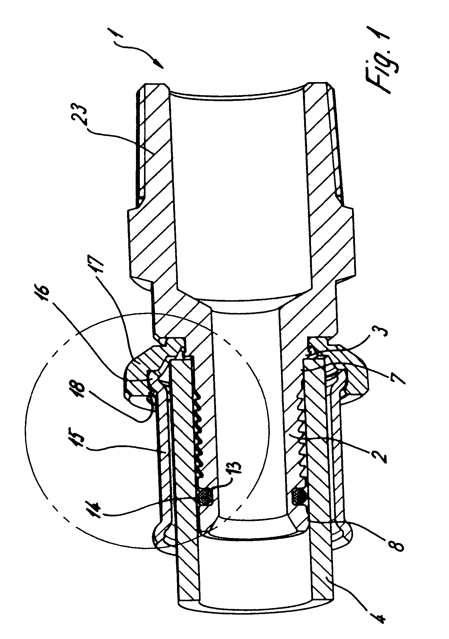
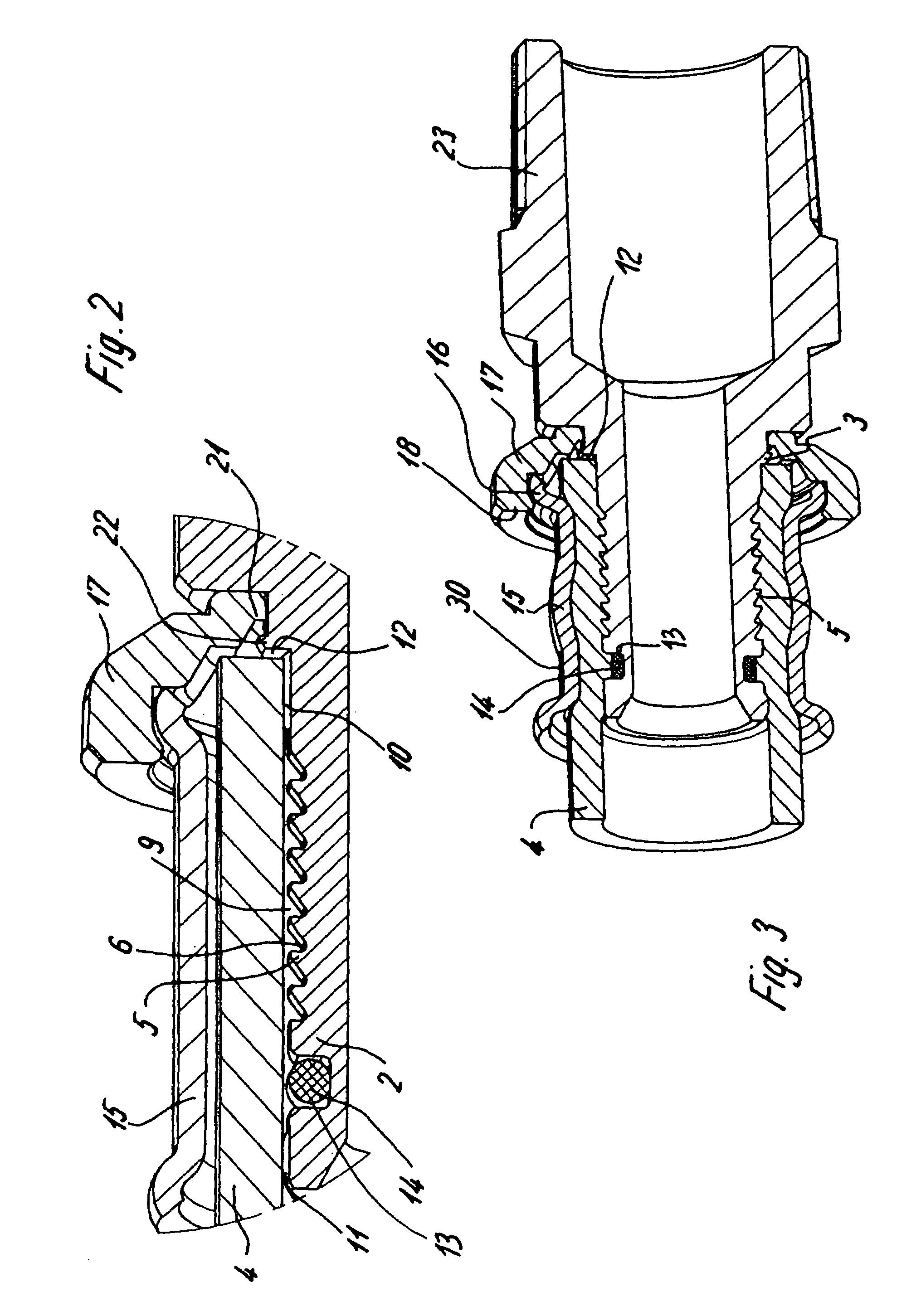
A connecting piece 1 comprises a stub 2 and a connection part 23 which is situated on the opposite side and may be constructed as a fitting or connecting device for connecting another component. The connecting piece 1 may be made of metal or of a plastic material.

The stub 2 can be inserted into a pipe 4 made of a plastic material, of a composite material or of metal. A stop 3 is on the stub 2, to a defined insertion depth of pipe 4. The stub 2 has an essentially ring-shaped cross-section and has profilings in the form of ribs 5 and grooves 6 on its outer circumferential surface, which also have a ring-shaped cross-section.

Spacers 7 and 8, which are also provided on the stub 2, are form-lockingly or with a certain clamping held against an interior wall of the pipe 4. Once spacer 7 is provided adjacent to the stop 3, and one spacer 8 is constructed at the extreme end of the stub 2. As a result of the spacers 7 and 8, the center area of the stub 2 with the profilings 5 and 6 is arran...


PUM

PropertyMeasurementUnit
Pressureaaaaaaaaaa
Diameteraaaaaaaaaa

Abstract

A connecting piece for establishing a connecting arrangement for a pipe which can be pressed together comprises a stub which can be inserted into a pipe. Profilings for the pressing-together with the pipe and a stop are on the stub. At least one radially projecting spacer is provided on the stub. The spacer defining a gap for forming a flow duct between the stub and the pipe. The spacer may have an interruption for forming part of the flow duct.

Description

BACKGROUND AND SUMMARY OF THE INVENTION The present invention relates to a connecting piece for establishing a connecting arrangement which can be pressed together, having a stub which can be inserted into a pipe and on which profilings are provided for the pressing-together with the pipe and which can be pushed into the pipe to a stop. In the prior art, supporting pipes constructed as a connecting piece were suggested, which supporting pipes are pushed into a pipe for establishing a pressed connection. For this purpose, the supporting pipe has a stub whose outer circumference corresponds approximately to the inner circumference of the pipe. For establishing a pressed connection, a pressure sleeve is placed around an end section of the stub and this pressure sleeve is then pressed onto the pipe so that the pipe made of a plastic or a composite material is durably held against the supporting pipe in a pressed manner in order to obtain a secure sealing. Such supporting pipes and conne...

Claims


Application Information

Patent Timeline
IPC IPC(8): F16L13/14F16L33/207F16L33/20
CPCF16L13/143F16L13/148F16L33/2078Y10T29/49913F16L2201/10
Inventor VIEGENER, WALTER
Owner FRANZ VIEGENER II GMBH & CO KG
Learn More