Self-spreading chemical barrier composition and injection method for dissolved-vug reservoirs
A karst cave type and composition technology, applied in chemical instruments and methods, drilling composition, earthwork drilling and mining, etc., can solve problems such as inappropriateness, achieve good airtightness, simple construction, and avoid the effect of synthetic technology
- Summary
- Abstract
- Description
- Claims
- Application Information
AI Technical Summary
Problems solved by technology
Method used
Image
Examples
Embodiment 1
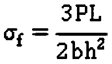
[0059] Add 0.6g of divinylbenzene, 0.3g of di-tert-butyl peroxide, and 0.1g of TEMP to 99g of styrene monomer, stir evenly to make it evenly mixed, put the obtained chemical separator material in an aluminum-capped sample bottle, and put the its sealed. Place the sample bottle in a high temperature tank, add an appropriate amount of water (the water level is flush with the height of the solution in the sample bottle) into the high temperature tank, and seal it. The above-mentioned chemical separator is obtained by placing the high temperature tank in an oil bath with a formation temperature of 130°C to polymerize the raw materials. The polymerization time of the chemical separator material at 130° C. is 5 hours, and the obtained chemical separator has a bending strength of 73.42 MPa after testing.
Embodiment 2
[0061] Add 0.5g of divinylbenzene, 0.4g of di-tert-butyl peroxide, and 0.1g of TEMP to 99g of styrene monomer, stir to make it evenly mixed, put the obtained chemical separator raw material in an aluminum-capped sample bottle, and put the its sealed. Place the sample bottle in a high temperature tank, add an appropriate amount of water (the water level is flush with the height of the solution in the sample bottle) into the high temperature tank, and seal it. The high temperature tank is placed in an oil bath with a formation temperature of 130°C to allow the raw materials to polymerize to obtain a chemical separator. The polymerization time of the chemical separator material at 130° C. is 9 hours, and the obtained chemical separator has a bending strength of 71.84 MPa after testing.
Embodiment 3
[0063] Add 0.6g of divinylbenzene, 0.35g of di-tert-butyl peroxide, and 0.05g of TEMP to 99g of styrene monomer, stir evenly to fully dissolve, and place the obtained chemical separator material in an aluminum-capped sample bottle. its sealed. Place the sample bottle in a high temperature tank, add an appropriate amount of water (the water level is flush with the height of the solution in the sample bottle) into the high temperature tank, and seal it. The above-mentioned chemical separator is obtained by placing the high temperature tank in an oil bath with a formation temperature of 130°C to polymerize the raw materials. The polymerization time of the chemical separator material at 130° C. is 12 hours, and the obtained chemical separator has a bending strength of 73.08 MPa after testing.
PUM
| Property | Measurement | Unit |
|---|---|---|
| density | aaaaa | aaaaa |
| bending strength | aaaaa | aaaaa |
| bending strength | aaaaa | aaaaa |
Abstract
Description
Claims
Application Information
 - R&D Engineer
- R&D Manager
- IP Professional
- Industry Leading Data Capabilities
- Powerful AI technology
- Patent DNA Extraction
Browse by: Latest US Patents, China's latest patents, Technical Efficacy Thesaurus, Application Domain, Technology Topic, Popular Technical Reports.
© 2024 PatSnap. All rights reserved.Legal|Privacy policy|Modern Slavery Act Transparency Statement|Sitemap|About US| Contact US: help@patsnap.com


