
A low-damage perovskite solar cell and packaging method thereof

A solar cell and perovskite technology, applied in circuits, electrical components, photovoltaic power generation, etc., can solve the problems of perovskite solar cell damage, solar cell damage, and low barrier, so as to avoid photoelectric conversion efficiency and improve universal application performance and high encapsulation efficiency

Active Publication Date: 2020-05-05
WUHAN UNIV OF TECH
View PDF8 Cites 0 Cited by
  • Summary
  • Abstract
  • Description
  • Claims
  • Application Information

AI Technical Summary

Problems solved by technology

Chinese patent CN105932164A forms a lead sulfide protective layer by coating a sulfur-containing ion solution on the lead halide perovskite film, which significantly improves the humidity resistance stability of the device. The problem of damage caused by mining solar cells
In the above patent, a layer of lead sulfide film is coated on the surface of the perovskite layer by the solution method, which will cause certain negative effects
Chinese patent CN205846020U adds an encapsulation layer (UV glue or sarin film) and a cover layer (ordinary glass or flexible film) to the perovskite battery to ensure the sealing, aging resistance and stability of the device to the greatest extent. Encapsulation with UV glue must also face the problem that some components in UV glue will cause damage to perovskite solar cells
In addition, general thin films (such as sarin thin films) have very low barrier to water, so they are not well applied in the field of perovskite solar cells.

Method used

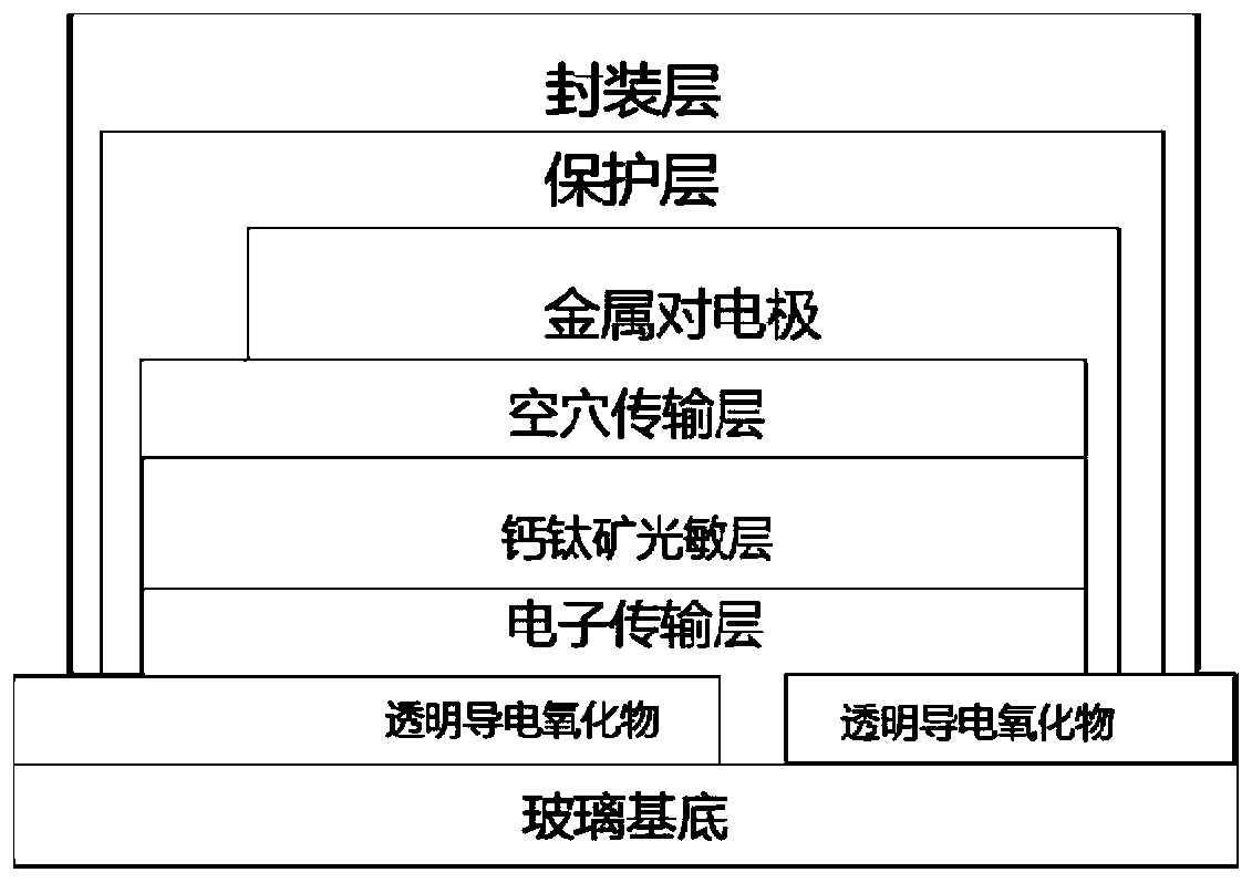
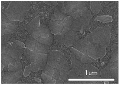

Image

  • A low-damage perovskite solar cell and packaging method thereof
  • A low-damage perovskite solar cell and packaging method thereof
  • A low-damage perovskite solar cell and packaging method thereof

Examples


Embodiment 1-6

[0029] 1) Using the same process method to prepare a batch of structures as FTO / TIO 2 / MAPB 3 / Spiro-OMeTAD / Au perovskite solar cells, as far as possible to ensure that the performance of each cell is consistent, and the difference is small.

[0030] 2) Place the same batch of prepared batteries on the sample stage of the evaporation apparatus, and evaporate a layer of molybdenum oxide protective layer on the surface of the batteries, with thicknesses of 5, 10, 20, 30, 60, and 100 nm respectively, which are recorded as Example 1 -6.

[0031] 3) At AM 1.5G, 100mW / cm 2 Under simulated sunlight, the photoelectric efficiencies of cells with different thicknesses of molybdenum oxide protective layers (Examples 1-6) and without evaporation of molybdenum oxide protective layers (Comparative Example 1) were tested.

[0032] 4) Place the above battery on the magnetron sputtering sample stage, and sputter a layer of Al 2 o 3 Ceramic encapsulation material, the thickness of the enca...

Embodiment 7-10

[0040] 1) Using the same process method to prepare a batch of structures as FTO / TIO 2 / MAPB 3 / Spiro-OMeTAD / Au perovskite solar cells, as far as possible to ensure that the performance of each cell is consistent, and the difference is small.

[0041] 2) Place the same batch of prepared batteries on the sample stage of an evaporation apparatus, and evaporate a protective layer of molybdenum oxide on the surface of the batteries with a thickness of 60 nm.

[0042] 3) Move the above battery to the magnetron sputtering sample stage, and sputter aluminum oxide with a thickness of 100nm, 300nm, 500nm, and 700nm (respectively referred to as Examples 7-10).

[0043] 4) At AM 1.5G, 100mW / cm 2 Under simulated sunlight, the initial photoelectric efficiencies of the cells of Examples 7-10 were tested and normalized. The batteries of Examples 7-10 and Comparative Example 2 were placed together in an environmental chamber for a stability test. The test conditions were a temperature of 30...

Embodiment 11

[0046] 1) Using the same process method to prepare a batch of structures as FTO / TIO 2 / MAPB 3 / Spiro-OMeTAD / Au perovskite solar cells, as far as possible to ensure that the performance of each cell is consistent, and the difference is small.

[0047] 2) Place the same batch of prepared batteries on the sample stage of an evaporation apparatus, and evaporate a protective layer of molybdenum oxide on the surface of the batteries with a thickness of 60 nm.

[0048] 3) Place the above battery on the magnetron sputtering sample stage, and sputter a layer of SiN X Ceramic encapsulation material, the thickness of the encapsulation layer is 500nm.

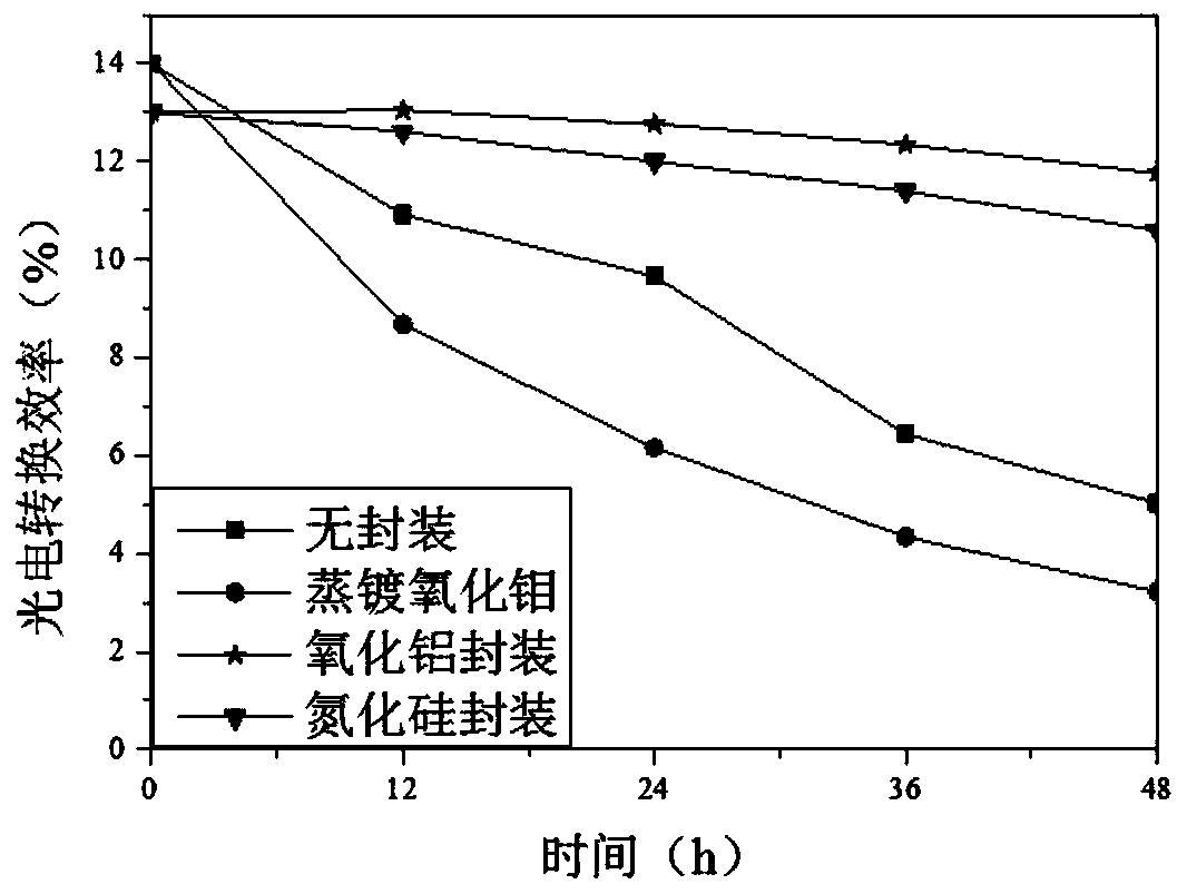
[0049] 4) The packaged battery is placed in an environmental chamber for a stability test, and the test conditions are 30° C., 30% humidity, and no light. Then at AM 1.5G, 100mW / cm 2 Under the simulated sunlight, the photoelectric efficiency of the above-mentioned battery is tested over time, and the results are as follows: figure 2 ...


PUM

PropertyMeasurementUnit
thicknessaaaaaaaaaa
thicknessaaaaaaaaaa
thicknessaaaaaaaaaa

Abstract

The invention relates to a low-damage perovskite solar cell and its packaging method. The perovskite solar cell includes a bottom-up conductive base layer, an electron transport layer, a perovskite light-absorbing layer, an electron transport layer, and a metal electrode layer , inorganic protective layer and ceramic encapsulation layer. The present invention mainly solves the problem that the current packaging method is easy to cause irreversible damage to the battery and cause a serious drop in battery efficiency. The inorganic protective layer is evaporated on the surface of the battery by using a thermal evaporation process with low energy, and then the magnetron sputtering method is used. The ceramic encapsulation layer is then formed, and the existence of the inorganic protective layer can minimize the damage to the perovskite solar cell caused by sputtering. Practice shows that the perovskite solar cell produced by the encapsulation method of the present invention has stable performance, high efficiency and low attenuation, and is especially suitable for encapsulation of large-area cell components.

Description

technical field [0001] The invention relates to the technical field of perovskite solar cells, in particular to a low-damage perovskite solar cell and a packaging method thereof. Background technique [0002] Organic-inorganic hybrid perovskite solar cells have attracted much attention in recent years due to their excellent photoelectric performance, and their photoelectric conversion efficiency has soared from the initial 3% to 22%, and the preparation cost is low and the process is simple. Photovoltaic devices. However, because it contains organic components, perovskite solar cells have poor tolerance to temperature, humidity and atmospheric environment. The invasion of the above factors will lead to the degradation of perovskite solar cells and a sharp decline in photoelectric performance. The stability of the battery seriously restricts its further development and application. [0003] In addition, in thin-film photovoltaic devices, such as copper indium gallium seleni...

Claims


Application Information

Patent Timeline
Patent Type & Authority Patents(China)
IPC IPC(8): H01L51/42H01L51/44H01L51/48
CPCH10K71/00H10K30/10H10K30/88Y02E10/549
Inventor 彭勇何江刘三万
Owner WUHAN UNIV OF TECH
Learn More