Eureka AIR delivers breakthrough ideas for toughest innovation challenges, trusted by R&D personnel around the world.

Temperature gradient energy storage heat exchanger

A temperature gradient and heat exchanger technology, applied in heat exchanger types, indirect heat exchangers, heat storage equipment, etc., can solve the problem of not considering the volume change of phase change materials, low heat transfer efficiency of smooth metal plates, and production safety Hidden dangers and other problems, to achieve the effect of solving the uneven energy distribution time and space, improving energy recovery and utilization rate, and occupying a small area

Pending Publication Date: 2018-08-17
SOUTH CHINA UNIV OF TECH
View PDF13 Cites 20 Cited by
  • Summary
  • Abstract
  • Description
  • Claims
  • Application Information

AI Technical Summary

Problems solved by technology

Patent No. CN206113738 "A Heat Storage Plate and Heat Storage Device" provides a way to use two metal plates to encapsulate phase change materials to form a heat storage plate, and stack multiple heat storage plates to form a heat storage device. The advantage is that the structure is simple The heat storage is large, and the disadvantage is that the heat transfer efficiency of the smooth metal plate is low, and the volume change produced by the phase change material during the phase transition is not considered, which has certain hidden dangers in production safety

Method used


Image

  • Temperature gradient energy storage heat exchanger
  • Temperature gradient energy storage heat exchanger
  • Temperature gradient energy storage heat exchanger

Examples


Embodiment

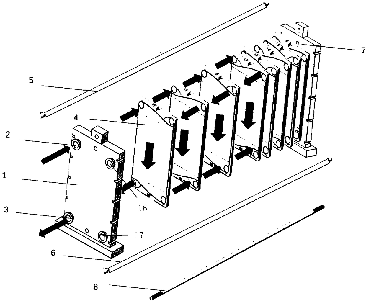
[0036] Such as figure 1 with Image 6 As shown, a temperature gradient energy storage heat exchanger includes a front splint 1, a rear splint 7, and at least two groups of plates 4 that are sequentially sealed and stacked between the front splint 1 and the rear splint 7 to form a fluid channel. An upper guide rod 5 and a lower guide rod 6 are respectively fixed between the upper and lower ends of the front splint 1 and the rear splint 7 , and the front splint 1 , the rear splint 7 and the plate 4 are clamped and connected by a plurality of fastening bolts 8 . The four corners of the front splint 1 are provided with a circular hot fluid inlet 2, a cold fluid outlet 3, a first exhaust hole 16, and a first sewage outlet 17, and the four corners of the rear splint 7 are provided with a circular cold fluid inlet 9, The hot fluid outlet 10, the second exhaust hole 18, the first sewage outlet 19, the four corners of the plate 4 are correspondingly provided with a circular fluid flow...


PUM


Abstract

The invention discloses a temperature gradient energy storage heat exchanger. The temperature gradient energy storage heat exchanger comprises a front clamping plate, a rear clamping plate and at least two sets of plates overlapped between the front clamping plate and the rear clamping plate to form fluid channels in a sealed mode in sequence. The four corners of the front clamping plate, the fourcorners of the rear clamping plate and the four corners of the plates are provided with circular fluid through holes correspondingly. The spaces inside the at least sets of the plates are filled withthe same phase change materials. The phase change temperatures of the phase change materials in the different sets of the plates decrease progressively in the fluid flowing direction. The temperaturegradient energy storage heat exchanger gives full play to the advantages of a plate heat exchanger such as high heat transfer coefficient, small occupied space, light weight and convenient manufacturing and achieves the purpose of improving the energy utilization efficiency through combination with the phase change materials with the characteristics of large heat storage capacity, environmental protection and selection diversity. The operational suitability is improved through independent cold and hot fluid channels. The temperature gradient energy storage heat exchanger has the advantages ofbeing large in energy storage density, convenient to operate and high in adaptability and can be applied to the fields of solar thermal collectors, heat pump heat collectors and industrial waste heatrecovery.

Description

technical field [0001] The invention relates to a temperature gradient energy storage heat exchanger, which is used for storing and utilizing heat energy, and belongs to the field of energy saving and environmental protection. Background technique [0002] With the rapid development of economy and society since the Industrial Revolution, the energy challenges faced by human beings have become increasingly severe. Phase change materials refer to substances that change the state of matter and provide latent heat with temperature changes, and are an effective method to improve energy utilization efficiency. As a common heat exchange device, the plate heat exchanger is widely used in various occasions, and the organic combination of the two will play a vital role in the efficient use of energy. [0003] At present, there is no energy storage heat exchanger with temperature gradient on the market. Consult relevant information, such as patent number CN206755314 "Energy Storage St...

Claims


Application Information

Patent Timeline
Patent Type & Authority Applications(China)
IPC IPC(8): F28D20/02
CPCF28D20/021Y02E60/14
Inventor 张正国王前蒿方晓明
Owner SOUTH CHINA UNIV OF TECH
Why Eureka
Eureka Blog
Learn More