
Illumination region control device and control method for LED phototherapy device

A technology of irradiation area and control device, which is applied in the field of LED phototherapy equipment irradiation area control device, can solve the problems of increased system complexity and cost, complex column latches, single-chip row and column drivers, and low light output intensity, and achieve simple image processing Ease of operation, image processing is simple and easy, and the effect of simple circuit structure

Pending Publication Date: 2018-08-03
INST OF BIOMEDICAL ENG CHINESE ACAD OF MEDICAL SCI
View PDF12 Cites 2 Cited by
  • Summary
  • Abstract
  • Description
  • Claims
  • Application Information

AI Technical Summary

Problems solved by technology

[0007] (1) This patent uses the traditional graphic segmentation-image recognition method to identify the lesion area, which requires complex graphic processing equipment and algorithms for calculation, which not only increases the complexity and cost of the system, but also the algorithm calculation will occupy a large number of machines time, it is difficult to update the shape and size of the irradiation area in real time;
[0008] (2) The row-by-row and column-by-column scanning method adopted in this patent determines that its utilization efficiency of LED is relatively low, and the light output intensity is low
Even if a latch is used to alleviate this contradiction, only one column of LED lights will be lit at a certain moment, and it is difficult to light up the LED light-emitting surface similar in shape to the lesion area at the same time
This results in a low power density of the light source, which cannot meet the actual demand for light power density of photodynamic therapy;
[0009] (3) With the improvement of image precision, the number of LEDs has increased greatly, which makes the column latches, single-chip microcomputers, row and column drivers required by this patent more complex, and the difficulty of the circuit increases exponentially.

Method used


Image

  • Illumination region control device and control method for LED phototherapy device

Examples


Embodiment

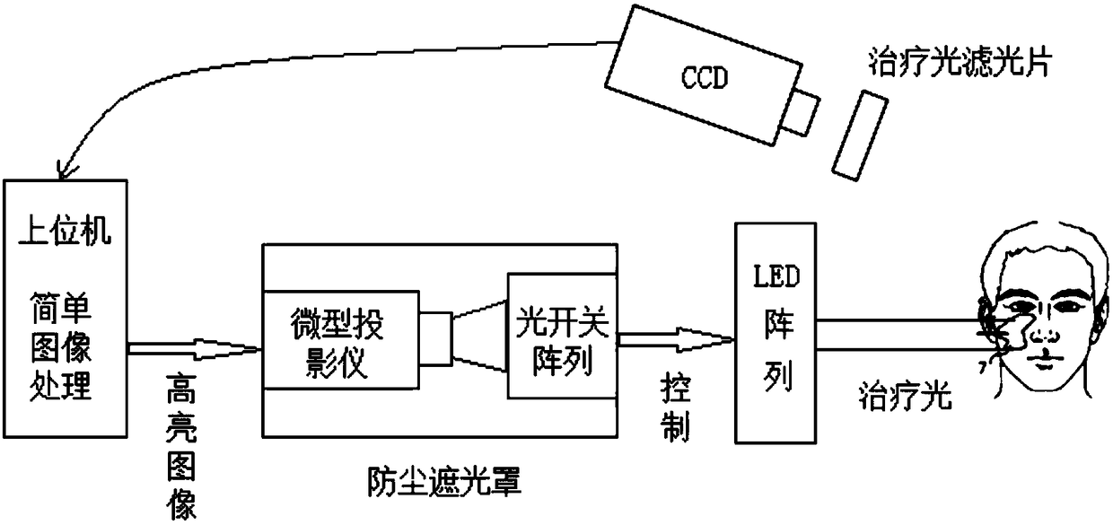
[0038]Precise photodynamic therapy for port wine stains: images of port wine stains are captured by the imaging CCD and uploaded to the host computer. Since the color of port wine stains is light red, dark red or purple red, the pixels with the above colors in the image can be set as white highlights, while the pixels of other normal tissues can be set as black, so that Obtain a highlighted image of the lesion area. The highlighted image of the lesion area is projected onto the optical switch array by the micro-projector, so that the optical switch corresponding to the position of the lesion area in the optical switch array is turned on, thereby driving the LED light at the corresponding position of the high-power LED array to light up, forming a precise photodynamic force for port wine stains Healing light source.


PUM


Abstract

The invention discloses an illumination region control device and control method for an LED phototherapy device. The control device comprises a host computer connected with an imaging CCD and a microprojector. The light output port of the micro projector is provided with an optical switch array, An LED array for outputting therapeutic light is disposed directly in front of the optical switch array. The optical switches in the optical switch array and the LED lights in the LED array have the same number and corresponding positions. One end of each optical switch is connected in series with thecorresponding LED light, and the other end of each optical switch is connected to ground. One end of each LED light is connected in series with the corresponding optical switch, and the other end ofeach LED light is connected to the level. After obtaining the image of a focus area, the control device converts the image into a highlighted image and projects the highlighted image onto the opticalswitch array, and the optical switch array turns on the LED array light source so that a therapeutic light source having consistent shape of the light-emitting area and highlighted image is formed, thereby achieving the control of a precise phototherapy to illumination area control.

Description

technical field [0001] The invention belongs to the field of medical equipment, and more specifically relates to a control device and a control method for an irradiation area of ​​an LED phototherapy equipment. Background technique [0002] Precise photodynamic therapy depends on whether the spot of laser irradiation matches the shape of the lesion. The better the match between the spot and the shape of the lesion, the less damage to normal tissues. [0003] At present, the method of controlling the shape of the irradiation area is mainly to use optical devices to shape the beam after the light is emitted, or to partially block the beam by using a diaphragm or a shading sheet, or to use a combination of the two to obtain a specified shape and irradiation area. uniform spot. [0004] Patent CN201420618502.6 introduces a laser spot shape adjustment device composed of a mirror frame, a beam expander input mirror, a diaphragm, a beam expander output mirror, a flat-top diffracti...

Claims


Application Information

Patent Timeline
IPC IPC(8): A61N5/06
CPCA61N5/062A61N2005/0665A61N2005/0642A61N2005/0652A61N2005/0626
Inventor 董晓曦李迎新阴慧娟杨基春黄河张建吴金鹏孙美秀李宏霄
Owner INST OF BIOMEDICAL ENG CHINESE ACAD OF MEDICAL SCI
Learn More