Panel drying device for wood industry

A drying device and plate technology, applied in drying, drying machine, veneer drying, etc., can solve the problems of serious heat loss, reduce the cost of plate drying, reduce the efficiency of plate drying, etc., and achieve good drying effect , High working efficiency and high thermal efficiency

Pending Publication Date: 2018-07-31
浙江浔园家居股份有限公司
View PDF3 Cites 3 Cited by
  • Summary
  • Abstract
  • Description
  • Claims
  • Application Information

AI Technical Summary

Problems solved by technology

[0002] In the process of wood processing, the drying treatment of boards has become an important step in the processing of boards. The existing board drying treatment device usually uses a heat pressing plate for drying, so that it can fully contact with the boards, which can ensure that the boards are dry during drying. The heat is even during the process, but the heat pressing plate is used for drying, and the plates need to be placed in batches, which reduces the efficiency of the plate drying, and after the drying is completed, the temperature needs to be cooled quickly to realize the removal of the plates and the release of the next batch of plates. Not only the heat loss is serious, but also it is not suitable for the continuous production and processing of large batches of plates
During the drying process of the conventional drying furnace, the heat in the furnace is directly discharged with the flue gas, and the waste heat of the flue gas cannot be effectively used. After the plate is dried, it carries a large amount of heat output, and the waste heat of the plate cannot be recycled and saved. Reduce energy consumption and reduce plate drying costs

Method used


Image

  • Panel drying device for wood industry
  • Panel drying device for wood industry

Examples


Embodiment Construction

[0015] The present invention is not limited by the following examples, and specific implementations can be determined according to the technical solution and actual conditions of the present invention.

[0016] The present invention will be further described below in conjunction with embodiments and drawings:

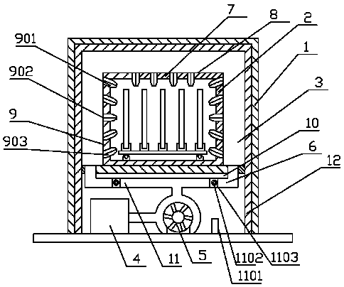
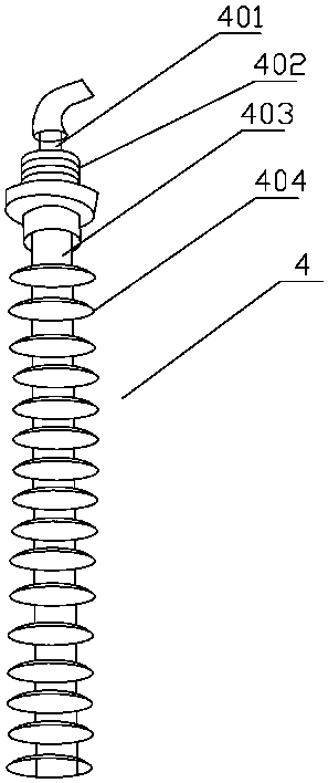
[0017] Such as figure 1 , 2 As shown, the wood board drying device includes an outer chamber body 1, an inner chamber body 2 and a hot air circulation system. A hot air flow space 3 is formed between the inner chamber body 2 and the outer chamber body 1. The hot air circulation system It includes a finned stainless steel heating tube 4, a fan 5, and an air duct 6 for introducing hot air into the hot air flow space 3. The stainless steel heating tube 4 is arranged inside the outer chamber 4, and the finned stainless steel heating tube 4 includes The high resistance electric heating alloy wire 401, the connecting screw 402, the electric heating tube 403, and the heat sink 404....


PUM


Abstract

The invention belongs to the technical field of wood industry processing, in particular to a panel drying device for wood industry. The panel drying device for wood industry comprises an outer room body, an inner room body and a hot air circulating system, wherein a hot air flowing space is formed between the inner room body and the outer room body; the hot air circulating system comprises a stainless steel heating tube with a fin, a fan and an air duct; the stainless steel heating tube is arranged on the inner side of the outer room body; the stainless steel heating tube with the fin is composed of a high resistance electric heating alloy wire, a connecting screw, an electric heating tube and a heat-dissipating fin; the high resistance electric heating alloy wire is arranged on the uppersurface of the connecting screw; the connecting screw is connected to the electric heating tube; the electric heating tube is arranged in the heat-dissipating fin; and an air guide tube unit for guiding hot air into the inner room body to dry panels is arranged on the inner room body. By generating and introducing hot air to the hot air flowing space by means of the hot air circulating system to dry the panels placed in the inner room body all around, the panel drying device for wood industry is good in drying effect and high in work efficiency. The electric heating efficiency is high by adopting the stainless steel heating tube with the fin.

Description

Technical field [0001] The invention belongs to the technical field of wood industry processing, and particularly relates to a board drying device for wood industry. Background technique [0002] In the wood processing process, the drying treatment of the board has become an important step in the processing of the board. The existing board drying treatment device usually uses a thermal pressure plate for drying to make it fully contact with the board and ensure that the board is dried. The heat is evenly heated during the process, but the heating plate is used for drying, and the plates need to be put in batches, which reduces the efficiency of plate drying. After the drying, the temperature needs to be quickly cooled to realize the removal of the plates and the placement of the next batch of plates. It is not only serious heat loss, but also not suitable for continuous production and processing of large quantities of plates. During the drying process of a conventional drying ov...

Claims


Application Information

Patent Timeline
Patent Type & Authority Applications(China)
IPC IPC(8): F26B9/06F26B21/00F26B25/06F26B25/12
CPCF26B9/066F26B21/001F26B21/004F26B25/063F26B25/12F26B2210/14
Inventor 储茂斌
Owner 浙江浔园家居股份有限公司
Why Eureka
Try Eureka