
Method and device for preparing nitrogen-doped carbon nanotubes by using microwave vapor deposition

A technology for preparing a device and carbon nanotubes, applied in the field of nanomaterials, can solve the problems of difficult control of reaction time and degree of reaction, many surface defects, small diameter of the tube, etc., and achieves microwave power tunability, low deposition pressure, An effect that increases the chance of ionization

Inactive Publication Date: 2018-06-22
WUHAN INSTITUTE OF TECHNOLOGY
View PDF3 Cites 4 Cited by
  • Summary
  • Abstract
  • Description
  • Claims
  • Application Information

AI Technical Summary

Problems solved by technology

[0003] Studies have shown that the diamagnetism of nitrogen-doped carbon nanotubes will decrease at the transition temperature of 910K and 1120K, but the related research results are not the same. The main reason is that the interior of the carbon nanotubes is a nanoscale hollow structure, but However, problems such as the small diameter of carbon nanotubes and many surface defects affect the practical application of carbon nanotubes.
There are many ways to prepare nitrogen and carbon nanotubes, most of which use chemical vapor deposition technology, but due to the difficulty in controlling the reaction time and degree of reaction, there are some impurity elements in the obtained product
Although the use of different nitrogen source substances, such as methane, nitrogen, etc., can effectively reduce other element impurity components in nitrogen-carbon nanotubes, the agglomeration of carbon nanotubes and carbon-containing components, as well as precursors and temperatures can affect the carbon Nitrogen doping amount of nanotubes and their ferromagnetism

Method used


Image

  • Method and device for preparing nitrogen-doped carbon nanotubes by using microwave vapor deposition
  • Method and device for preparing nitrogen-doped carbon nanotubes by using microwave vapor deposition
  • Method and device for preparing nitrogen-doped carbon nanotubes by using microwave vapor deposition

Examples


preparation example Construction

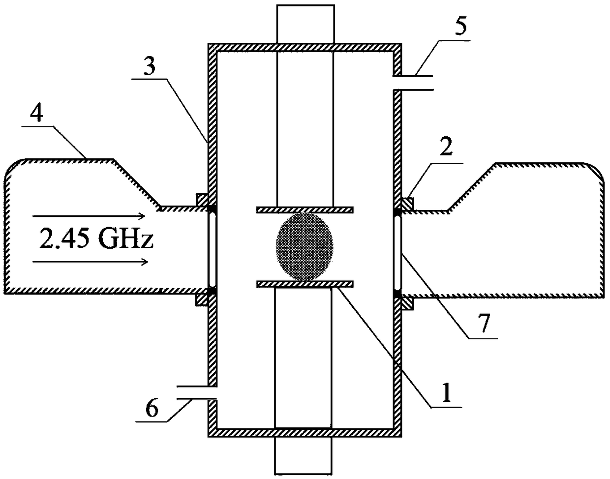
[0029] The schematic diagram of the preparation device of nitrogen-doped carbon nanotubes of the present invention refers to the attached figure 1 As shown, it includes a cavity 3, an air inlet 5, an air extraction port 6, a compressed rectangular waveguide 4, a quartz glass tube 7, and a microwave generator;

[0030] Inside the cavity, a substrate table 1 and a lifting mechanism are provided, and the substrate table 1 is installed on the lifting mechanism;

[0031] There are air inlets 5 and air outlets 6 at the upper and lower ends of the cavity;

[0032] The middle part of the cavity is provided with a quartz glass tube 7, and microwaves are transmitted in the cavity 3 through the quartz glass tube 7;

[0033] The cavity is fixed with a metal flange 2 that can move up and down. The upper metal flange 2 is located above the quartz glass tube 7, and the lower metal flange is located below the quartz glass tube. The cavity 3 is composed of the upper and lower metal flanges 2 ...

Embodiment 1

[0037] (1) Using ethanol and acetone solutions in sequence to ultrasonically clean the substrate to remove surface impurities. Subsequently, an appropriate amount of carbon nanotube powder sample is placed on the substrate at the center of the substrate stage and placed in a closed cavity, and then the metal flange is sealed to exclude air.

[0038] (2) Vacuumize the cavity, and feed nitrogen, adjust the nitrogen flow and air pressure (the air pressure of nitrogen in the cavity), and perform microwave irradiation;

[0039] (3) The gas in the chamber absorbs microwave energy to excite and generate plasma. The process parameters used are: nitrogen flow rate 50sccm, working pressure 2.0kPa;

[0040] (4) Introduce nitrogen gas, adjust the gas flow rate, and wait until the plasma state is stable. After the reaction, the microwave source was turned off, and after the cavity was cooled, the nitrided samples were taken out. The process parameters used in the experiment were: microwav...

Embodiment 2

[0044] (1) Using ethanol and acetone solutions in sequence to ultrasonically clean the substrate to remove surface impurities. Subsequently, an appropriate amount of carbon nanotube powder sample is placed on the substrate at the center of the substrate stage and placed in a closed cavity, and then the metal flange is sealed to exclude air.

[0045] (2) Vacuumize the cavity, and feed nitrogen, adjust the nitrogen flow and air pressure (the air pressure of nitrogen in the cavity), and perform microwave irradiation;

[0046] (3) The gas in the cavity absorbs microwave energy to excite and generate plasma. The process parameters used are: nitrogen flow rate 50 sccm, and working pressure 3.0 kPa.

[0047] (4) Introduce nitrogen gas from the gas inlet, control and adjust the gas flow rate, and wait until the plasma state is stable. After the reaction, turn off the microwave source, wait for the cavity to cool down, and take out the sample. The process parameters used in the experi...


PUM


Abstract

The invention discloses a method and device for preparing nitrogen-doped carbon nanotubes by using microwave vapor deposition. The method comprises the following steps that carbon nanotube powder is placed in a closed cavity, and the cavity is vacuumized; nitrogen gas is introduced to the cavity, the flow rate and air pressure of the nitrogen gas are adjusted, and meanwhile microwave irradiation is conducted to make the gas in the cavity absorb microwave energy and be excited to generate plasma; nitrogen atoms after plasma treatment can be doped into the surfaces and internal structures of carbon nanotubes to form the nitrogen-doped carbon nanotubes, and by controlling the microwave power and nitrogen doping time, the nitrogen carbon nanotubes with different nitrogen contents are obtained.A nitrogen gas source is subjected to plasma treatment by adopting a microwave plasma technology. Since the microwave power and the energy density are high and radical groups have high activity, thegas can be easily dissociated; the nitrogen carbon nanotubes prepared by means of the method are high in quality and purity and facilitates the test and characterization of ferromagnetic properties, optical properties and other properties, and prepared samples show good ferromagnetism.

Description

technical field [0001] The invention belongs to the technical field of nanometer materials, and in particular relates to a method for preparing nitrogen-doped carbon nanotubes by using microwave plasma chemical vapor deposition technology. Background technique [0002] Carbon nanotubes are seamless carbon nanotube one-dimensional nanomaterials formed by curling single-layer or multi-layer graphite sheets around the central axis at a certain helical angle. With the development of carbon nanotubes (CNTs) and carbon nanotubes doped with different types of elements, carbon nanotubes have attracted much attention due to their unique structure and excellent properties. When doped with different types of elements, The structure of the carbon nanotube hexacyclic ring will undergo certain changes to change or improve its performance. Carbon nanotube materials have a wide range of applications in electronic optical devices, electrochemistry, heat conduction and so on. Incorporating ...

Claims


Application Information

Patent Timeline
IPC IPC(8): C01B32/168
CPCC01B2202/20C01B2202/30
Inventor 赵洪阳方紫璇王欢马志斌
Owner WUHAN INSTITUTE OF TECHNOLOGY
Learn More