
Safety detection warning system

An early warning system and security detection technology, applied in the direction of alarms, instruments, etc., can solve the problems of open interface trouble, waste, supervision loopholes, etc., and achieve the effect of low price, simple structure and cost reduction.

Pending Publication Date: 2018-06-12
赵自强
View PDF5 Cites 9 Cited by
  • Summary
  • Abstract
  • Description
  • Claims
  • Application Information

AI Technical Summary

Problems solved by technology

[0005] (1) Single function
A single system has a single function and is implemented in a block-by-block manner, unable to comprehensively monitor common multi-type hazard sources
For example: fire alarm systems are basically installed in crowded places, but cannot detect flammable and explosive gases at the same time, resulting in huge waste and regulatory loopholes
[0006] (2) Information silos, out of touch with government regulation
These systems are isolated island systems, open interfaces are very troublesome, and it is difficult to collect data
Out of touch with the informatization of safety supervision, out of touch with the government's safety supervision public service, lack of connection with the management system of enterprises and the government, out of touch with the national "hidden danger investigation and governance system", and unable to implement the government's safety management system
[0007] (3) Lack of behavior supervision
Lack of supervision on the behavior of safety management personnel and safety operators, unable to form normalized supervision

Method used


Image

  • Safety detection warning system
  • Safety detection warning system
  • Safety detection warning system

Examples


Embodiment Construction

[0044] In order to make the objectives, technical solutions and advantages of the present invention clearer, the technical solutions of the present invention will be described in detail below. Obviously, the described embodiments are only a part of the embodiments of the present invention, rather than all the embodiments. Based on the embodiments of the present invention, all other implementations obtained by a person of ordinary skill in the art without creative work shall fall within the protection scope of the present invention.

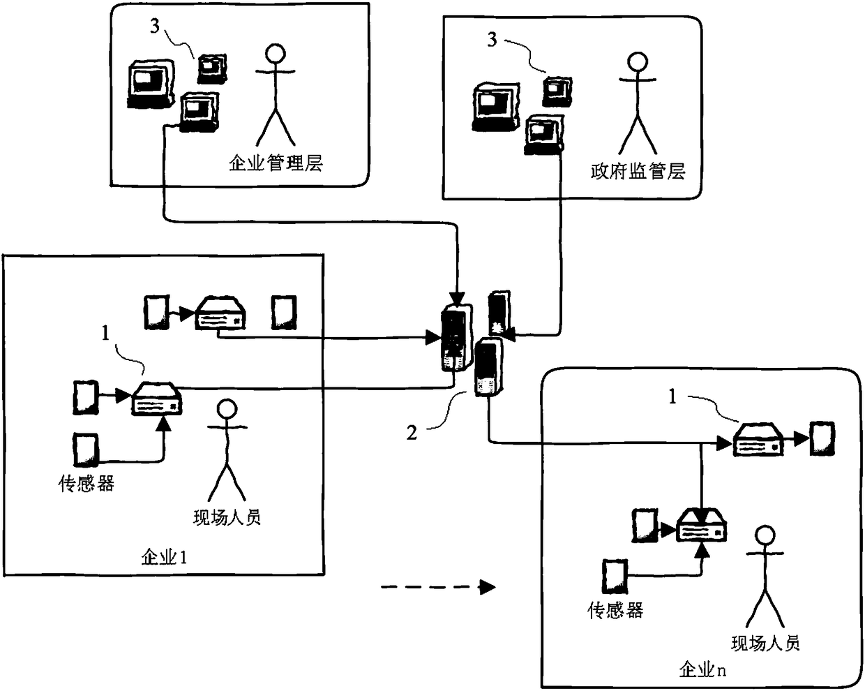
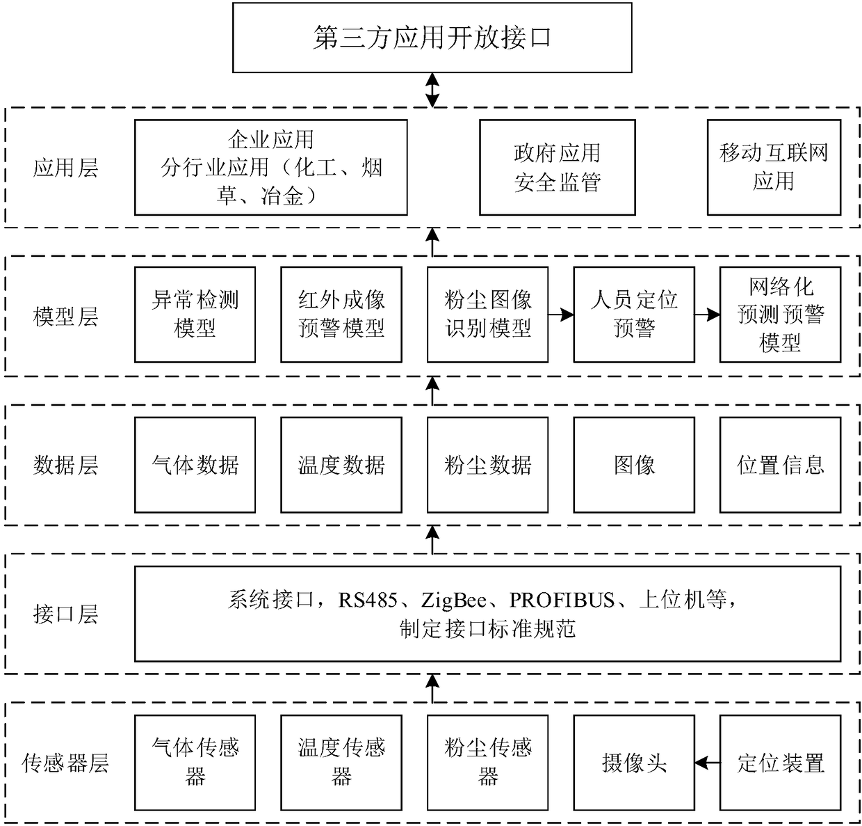
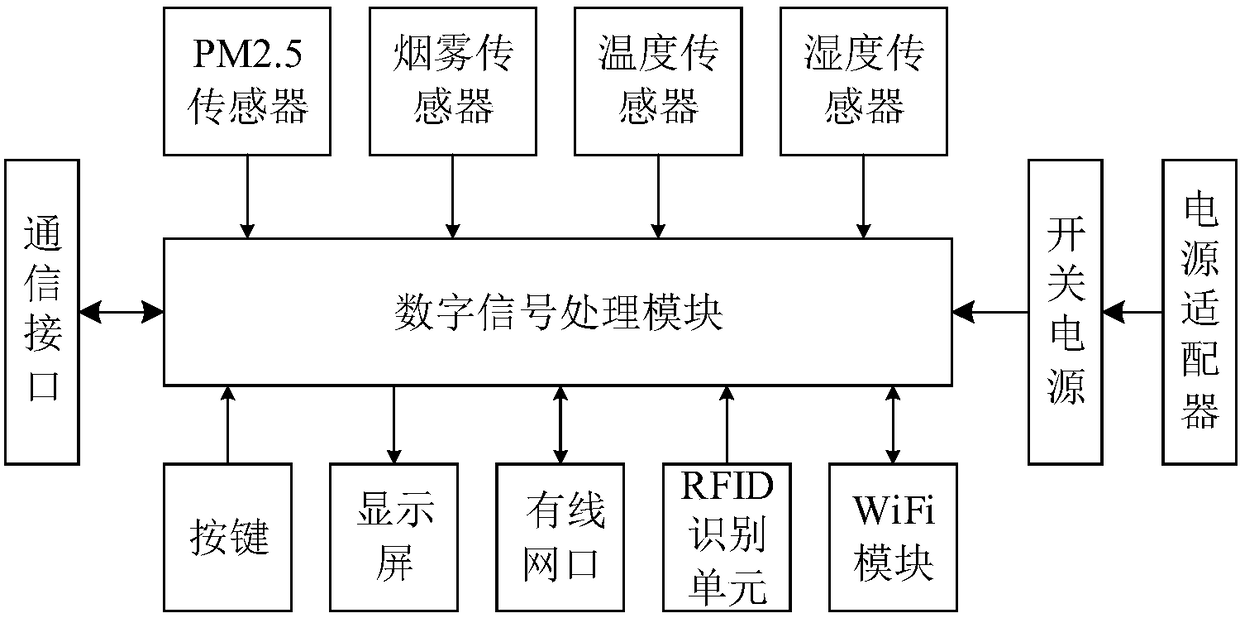
[0045] Such as figure 1 As shown, the present invention provides a safety detection and early warning system, which includes a field detection device 1, a cloud server 2 and a user terminal 3. The field detection device 1 collects information and uploads it to the cloud server 2; the user terminal 3 is connected to the cloud server 2 in communication. Wherein, the user terminal 3 is a smart phone or a tablet computer.

[0046] The cloud server 2 incl...


PUM


Abstract

The invention relates to a safety detection warning system which comprises field detection equipment, cloud servers and user terminals. Information can be acquired by the field detection equipment andcan be uploaded to the cloud servers by the field detection equipment; the user terminals are in communication connection with the cloud servers; the field detection equipment comprises power modules, information acquisition modules, processing modules and interaction modules; the information acquisition modules are used for acquiring environmental information of fields; the interaction modules are used for man-machine interaction and data uploading; collected data can be modeled and analyzed by the cloud servers according to different safety scenes, and safety production schemes can be generated by the cloud servers and can be pushed to the user terminals by the cloud servers; field inspection and evaluation standards are set, and warning information can be released to the user terminalsif detected data do not conform to the standards. The safety detection warning system has the advantages that solution of the safety detection warning system is low in cost; the safety detection warning system can be flexibly deployed and can be quickly popularized; the safety detection warning system is wide in application; government regulation and enterprise regulation are unified; entire-personnel regulation can be implemented; novel third-party safety regulation modes can be constructed; safety regulation application can be expanded.

Description

Technical field [0001] The invention belongs to the technical field of enterprise safety monitoring systems, and specifically relates to a safety detection and early warning system. Background technique [0002] For hardware technology, all kinds of detection sensor technology, communication technology RFID, on-site positioning technology, camera, information display screen, control button implementation and other technologies are mature and stable, but the market has not yet been able to achieve various detection Sensors, RFID, on-site location information, cameras, information display screens, and control buttons are integrated into a hardware device on a data acquisition chip. This makes a single set of safety monitoring systems have a single function and block implementation, and cannot deal with common multiple hazards. Comprehensive monitoring. With the accumulation of safety monitoring system problems and the government and society attaching importance to safety monitorin...

Claims


Application Information

Patent Timeline
Patent Type & Authority Applications(China)
IPC IPC(8): G08B27/00G08B19/00
CPCG08B19/00G08B27/006
Inventor 赵自强
Owner 赵自强
Learn More