
Manner of shortening scintillation response of luminescence centres and material of scintillator with shortened scintillation response

A scintillator material and scintillator technology, applied in luminescent materials, chemical instruments and methods, radiation measurement, etc., can solve the problems of insufficient light and low light quantity, and achieve the effect of reducing the scintillation response time

Active Publication Date: 2018-06-08
CRYTUR SPOL SRO +1
View PDF13 Cites 9 Cited by
  • Summary
  • Abstract
  • Description
  • Claims
  • Application Information

AI Technical Summary

Problems solved by technology

But in some usage examples even this value is not enough
[0010] Although there are faster scintillators than the above scintillators, such as BaF 2 , PbWO 4 or ZnO, but they are not used for practical applications, because the amount of light they provide is too low, that is, the amount of photons per 1 MeV of energy of ionizing radiation absorbed

Method used


Image

  • Manner of shortening scintillation response of luminescence centres and material of scintillator with shortened scintillation response
  • Manner of shortening scintillation response of luminescence centres and material of scintillator with shortened scintillation response
  • Manner of shortening scintillation response of luminescence centres and material of scintillator with shortened scintillation response

Examples


Embodiment 1

[0054] Example 1: Preparation of samples of YAG:Ce, YAG:Nd and YAG:Ce single crystal (YAG:Ce, Nd) co-doped with Nd

[0055] by Y 2 o 3 and Al 2 o 3 Binary oxides prepared with Y 3 al 5 o 12 A mixture consisting of CeO 2 and Al 2 o 3 prepared with Ce 3 al 5 o 12 A mixture consisting of Nd 2 o 3 and Al 2 o 3 Prepared with Nd 3 al 5 o 12 Composition of mixtures in which the purity of the materials used is 5N. After mechanical mixing, homogenize by shaking and compress into a mass by isostatic pressing. The blocks were sintered in air at 1400°C for 24 hours, then partially crushed and embedded in molybdenum crucibles. YAG:Ce, YAG:Nd and YAG:Ce,Nd single crystals were grown from the mixture by the Czochralski method in a hydrogen / argon protective atmosphere. The composition of the melts used for growth was chosen in such a way to compare their properties that the resulting crystals had Y 2.96 Nd 0.04 al 5 o 12 , Y 2.91 Nd 0.04 Ce 0.05 al 5 o 12 and Y ...

Embodiment 2

[0058] Example 2: Preparation of sample of YAG:Ce single crystal (YAG:Ce, Ho) co-doped with Ho

[0059] In a total amount of 5 g, Y with a purity of 5N 2 o 3 、Al 2 o 3 , CeO 2 and Ho 2 o 3 Binary oxides with formula Y 2.91 Ho 0.04 Ce 0.05 al 5 o 12 ratio is mixed. After mechanical mixing and grinding in a mortar, two-stage sintering was performed: in the first stage, sintering at 1300° C. in air for 24 hours; in the second stage, sintering at 1400° C. in air for 24 hours. The material is ground again in a mortar between individual steps. The powder was embedded in a molybdenum crucible, and the single crystal was pulled into a rod shape by the EFG method through a molybdenum die in a protective atmosphere of 70% argon / 30% hydrogen. Prepare Y in the same way 2.96 Nd 0.04 al 5 o 12 and Y 2.95 Ce 0.05 al 5 o 12 single crystals to compare their properties. A small disc with a thickness of 1 mm was cut out from the prepared single crystal rod with a diameter o...

Embodiment 3

[0061] Example 3: Preparation of samples of YAP:Pr single crystal and YAP:Pr single crystal co-doped with Gd (YAP:Pr, Gd)

[0062] According to Example 2, with Y 0.995 PR 0.005 AlO 3 , Y 0.985 Gd 0.01 PR 0.005 AlO 3 and Y 0.945 Gd 0.05 PR 0.005 AlO 3 The ratio of the chemical formula to mix Y with a purity of 5N 2 o 3 、Al 2 o 3 、Gd 2 o 3 and Pr 6 o 11 Binary oxides, YAP:Pr and YAP:Pr, Gd single crystals were similarly prepared and grown. Spectral and scintillation responses were tested similarly as in Example 2.

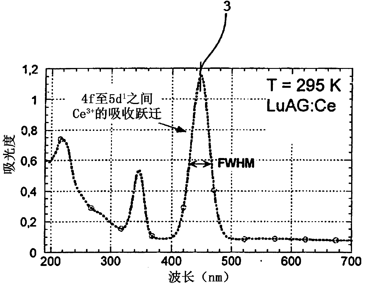
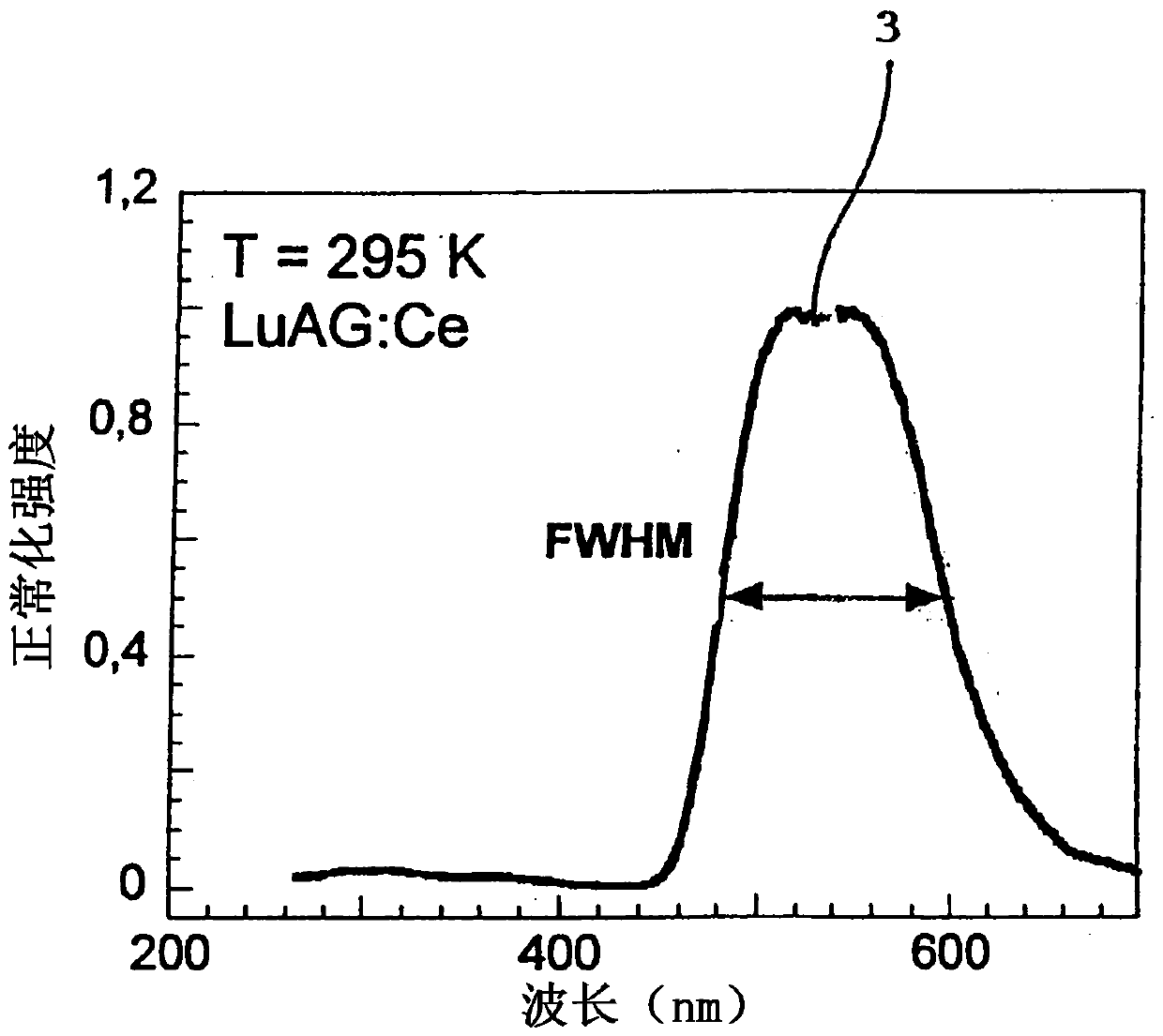
[0063] Figure 7 Show Pr 3+ Emission band in the center, marking the peak at 247nm 3 and in YAP:Pr scintillator with Pr 3+ Center-relative full width at half maximum (FWHM).

[0064]


PUM

PropertyMeasurementUnit
purityaaaaaaaaaa

Abstract

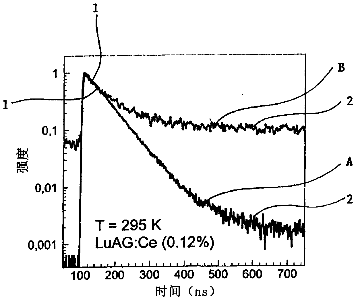
Problem to be solved: Currently, the known manner of shortening the scintillation response of scintillation material is to suppress the amplitude-minor slower components (2) of the scintillation response, whereas the possibilities of significant shortening of the amplitude-dominant component of the scintillation response in this manner are limited. Solution: The invention concerns the manner of shortening the scintillation response of scintillator luminescence centres which uses co-doping with Ce or Pr together with co-doping with ions from the lanthanoids, 3d transition metals, 4d transitionmetals or 5s2 or 6s2 ions group. Having had the luminescence centres electrons excited as a result of absorbed electromagnetic radiation, the scintillator created in this manner is capable of taking away a part of the energy from the excited luminescence centres via a non-radiative energy transfer, which results in a significant shortening of the time of duration of the amplitude-dominant component (1) of the scintillation response.

Description

technical field [0001] The present invention relates to methods of shortening the scintillation response of scintillators for detecting ionizing radiation, and to scintillator materials having a fast scintillation response to incident ionizing radiation. Background technique [0002] Scintillation material (that is, scintillator) can absorb ionized particles or photons, and the absorbed ionized particles or photons have sufficient energy to ionize its environment, that is, generally in the vacuum ultraviolet (above 7eV) or in the electromagnetic spectrum The much shorter wavelength region of the electromagnetic spectrum, and the scintillation material is capable of emitting ionizing particles or photons with lower energies in the relevant region of the electromagnetic spectrum. Absorption of ionizing radiation in any environment induces excited states of the electrons of the scintillator atoms, molecules or ions in the crystal lattice. In the so-called scintillation respons...

Claims


Application Information

Patent Timeline
Patent Type & Authority Applications(China)
IPC IPC(8): G01T1/202C09K11/08
CPCG01T1/202G21K4/00C09K11/7774C09K11/7701G01T1/2023
Inventor 金得里希·胡兹维卡卡雷尔·布拉泽克彼得·胡罗迪斯基马丁·尼克尔帕沃·波哈斯克
Owner CRYTUR SPOL SRO
Learn More