
Heat-superconducting plate and manufacturing technology thereof

A technology of superconducting heat and heat conducting plates, applied in the field of heat exchange, can solve the problems of low production efficiency, difficulty in high-efficiency mass production, cumbersome manufacturing methods, etc., and achieve the effect of simple manufacturing process

Pending Publication Date: 2018-04-13
BEIJING FULLLINK OREITH TECH CO LTD
View PDF8 Cites 0 Cited by
  • Summary
  • Abstract
  • Description
  • Claims
  • Application Information

AI Technical Summary

Problems solved by technology

[0003] The existing heat pipe structure is fixed, the heat dissipation is air-heat pipe heat dissipation, the heat dissipation efficiency is not high, and the heat conduction plate can directly contact with the heat dissipation device, which improves the heat transfer efficiency
A flat aluminum microporous heat pipe described in patent CN2014105908906 adopts a plate-shaped heat exchanger, which increases the contact area with the heat dissipation device. Low production efficiency, difficult to efficiently mass produce

Method used


Image

  • Heat-superconducting plate and manufacturing technology thereof
  • Heat-superconducting plate and manufacturing technology thereof
  • Heat-superconducting plate and manufacturing technology thereof

Examples


Embodiment Construction

[0016] In order to make the object, technical solution and advantages of the present invention clearer, the present invention will be further described in detail below with reference to the accompanying drawings and examples.

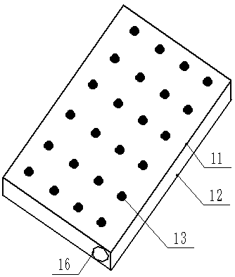
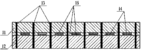
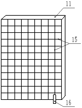
[0017] Such as figure 1 , 2 It is a schematic diagram of the heat conduction plate (1), and its manufacturing process includes the following steps:

[0018] 1. First make two rectangular metal plates by stamping or casting.

[0019] 2. Place the upper metal plate in the etching solution to etch the inner surface to form a well-shaped communication channel (15) that can smoothly circulate the working medium.

[0020] 3. Coat the well-shaped communication channel (15) in the upper metal plate and the inner surface of the lower metal plate with a liquid-absorbing film that can ensure that the working medium can flow smoothly between the upper and lower metal plates.

[0021] 4. Seal the two metal plates around and place a liquid filling tube (16) with a...


PUM


Abstract

The invention discloses a heat conducting plate mainly composed of an upper metal plate, a lower metal plate, a working medium and a liquid filling pipe. The upper metal plate and the lower metal plate are rectangular flat plates identical in size. After the upper metal plate and the lower metal plate are arranged in a vertically aligned manner, the peripheral edges of the upper metal plate and the lower metal plate are sealed through welding, then a metal shell is formed, and reinforcing points are welded at the middle position so that the strength of the shell is improved. A communicating channel shaped like a Chinese character 'jing' is etched on the inner surface of the upper metal plate and enables the work medium to flow, and the whole metal plate shell can be filled with the work medium in a one-off manner. The liquid filling pipe penetrates through the side face of the metal shell to communicate with the communicating channel shaped like the Chinese character 'jing', and therefore vacuumizing and work medium filling are convenient. The heat conducting plate has the advantages that the heat conducting plate has isotropy in the heat transfer directions, and the heat conducting plate can be used for heat dissipation of a point heat source, a line heat source and a face heat source; a manufacturing technology is simple, and mass production can be conducted; and the heat conducting plate can be produced into different shapes so as to adapt to cooling components. The heat conducting plate can be widely applied to heat dissipation of electronic products or constant-temperature heating of food or chemical equipment and can also be used as a heat exchanger.

Description

technical field [0001] The invention relates to the technical field of heat exchange, in particular to a superconducting heat plate. Background technique [0002] The current heat transfer elements mostly use heat pipes, which transfer heat through the phase-change latent heat of the working medium in the sealed vacuum tube shell. The medium inside the heat pipe is heated and evaporated in the heating section, and after rising to the upper part, it condenses and releases heat in the heat dissipation section. The heat transfer performance of the heat pipe is similar to the electrical conductivity of a superconductor, so it has the characteristics of large heat transfer capacity and high heat transfer efficiency. Because of its superior heat transfer performance and technical characteristics, it is widely used in the field of energy saving. At present, heat pipes are commonly used in equipment cooling, waste heat recovery, and fresh air systems. [0003] The existing heat pi...

Claims


Application Information

Patent Timeline
Patent Type & Authority Applications(China)
IPC IPC(8): F28D15/02F28F21/08
CPCF28D15/02F28F21/081
Inventor 祝长宇
Owner BEIJING FULLLINK OREITH TECH CO LTD
Learn More