Open-loop controllable high-precision rotation piezoelectric driving device and manufacturing method thereof

A manufacturing method and piezoelectric drive technology, applied in piezoelectric effect/electrostrictive or magnetostrictive motors, generators/motors, electrical components, etc., can solve the problem of increasing the complexity of the control system, affecting the operation stability, Reduce the drive efficiency and life and other problems, to achieve the effect of improving the electromechanical energy conversion efficiency, improving the load balance, and improving the excitation efficiency

Inactive Publication Date: 2018-03-13
TIANJIN UNIV
View PDF4 Cites 2 Cited by
  • Summary
  • Abstract
  • Description
  • Claims
  • Application Information

AI Technical Summary

Problems solved by technology

The stator usually works in the ultrasonic frequency band, and the stator and rotor rub against each other at a high relative speed, resulting in a significant temperature rise, which affects the operation stability and reduces the driving efficiency and life.
In addition, since the stator and rotor are in partial contact, the driving force is small
Mode splitting caused by structural periodicity (Wang S Y, Xiu J, Gu J, Xu J, Shen Z G. Prediction and suppression of inconsistent natural frequency and mode coupling of acylindrical ultrasonic stator, Proceedings of the Institution of Mechanical Engineers, Part C: Journal of Mechanical Engineering Science, 2010, 224(9), 1853-1861) and the adverse effects of harmonic drive signals, the contact state of the stator and rotor is constantly changing, resulting in inconsistent forward and reverse outputs, which increases the complexity of the control system
In addition, since the ratio of traveling wave velocity to rotor speed is not constant, it is difficult to implement open-loop control
In short, problems such as temperature rise, debris, lost rotation, small output, shifting operating point, low driving efficiency, short service life, asymmetric forward and reverse rotation, and difficulty in realizing open-loop control have seriously restricted the use of traditional ultrasonic motors in various applications. Applications in precision instruments
For those extreme working environments such as ultra-high speed, large overload and strong low temperature, its application is further restricted

Method used


Image

  • Open-loop controllable high-precision rotation piezoelectric driving device and manufacturing method thereof
  • Open-loop controllable high-precision rotation piezoelectric driving device and manufacturing method thereof
  • Open-loop controllable high-precision rotation piezoelectric driving device and manufacturing method thereof

Examples


Embodiment 1

[0042] An embodiment of the present invention provides a piezoelectric drive device using a single stator assembly or multiple stator assemblies with micro-tooth meshing, including: several piezoelectric actuators, a stator with internal teeth and a rotor with external teeth.

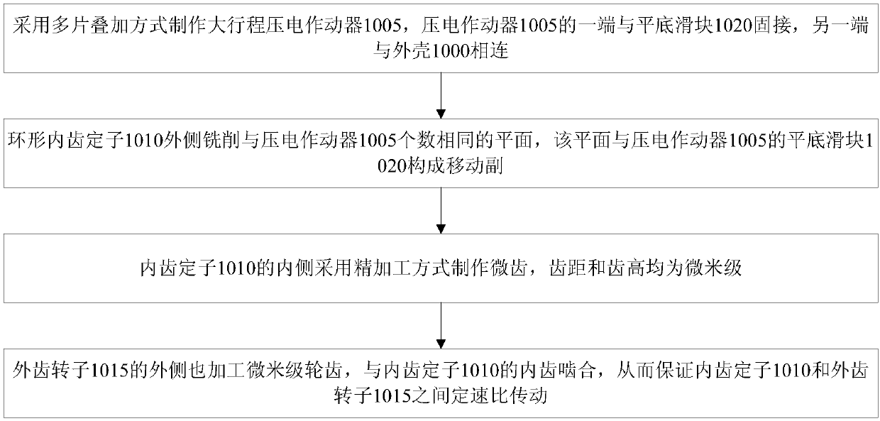
[0043] Among them, the piezoelectric actuator works in the d33 mode, and adopts the lamination type to increase the amplitude-changing stroke. The piezoelectric actuators are installed radially and evenly distributed at equal intervals along the circumferential direction. One end of the piezoelectric actuator is fixedly connected to the casing by bolts, and the other end is movably connected to the outer side of the internal tooth stator through a moving pair.

[0044] Among them, micro-teeth are processed on the inner side of the inner-toothed stator, which mesh with micro-tooths on the surface of the external-toothed rotor. Under the action of the AC signal, each piezoelectric actuator produces an as...

Embodiment 2

[0054] Combine below figure 1 The scheme in Example 1 is further introduced, see the following description for details:

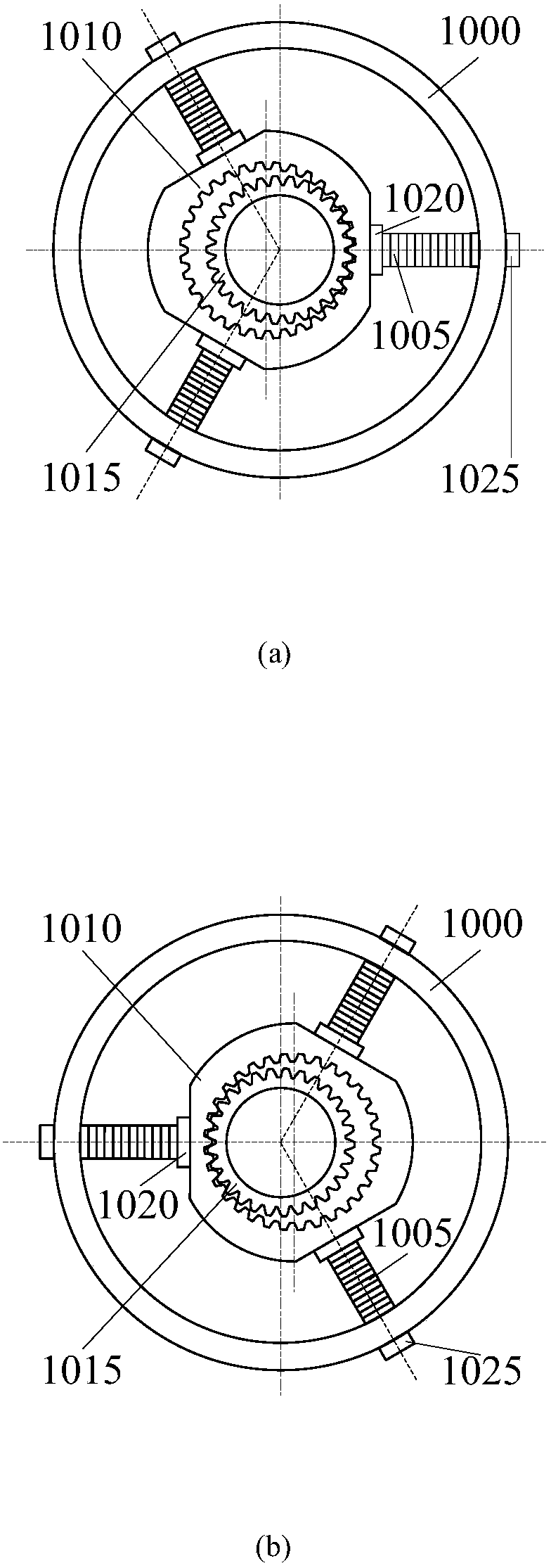
[0055] Such as figure 1 As shown in (a), this embodiment is composed of a housing 1000 , three piezoelectric actuators 1005 (constituting a first piezoelectric component), an internally toothed stator 1010 and an externally toothed rotor 1015 . Wherein, the laminated piezoelectric actuator 1005 is connected to the casing 1000 through bolts 1025 in the radial direction, and is in sliding contact with the internal tooth stator 1010 . In order to achieve force balance, each piezoelectric actuator 1005 is evenly distributed along the circumferential direction.

[0056] The structure of the second piezoelectric assembly (also composed of three piezoelectric actuators 1005) is basically the same as that of the first piezoelectric assembly, the only difference is the installation position of the piezoelectric actuators 1005, such as figure 1 (b) shown.

[0057...

Embodiment 3

[0065] Combine below figure 2 The scheme in Example 1 is further introduced, see the following description for details:

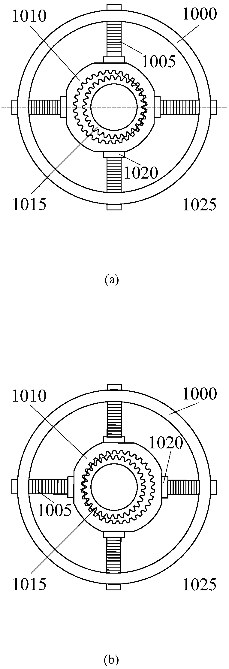
[0066] Such as figure 2 As shown in (a), this embodiment is composed of a housing 1000 , four piezoelectric actuators 1005 (constituting a first piezoelectric assembly), an inner-toothed stator 1010 and an outer-toothed rotor 1015 . Wherein, the laminated piezoelectric actuator 1005 is connected to the casing 1000 by bolts in the radial direction, and the actuators are evenly distributed and arranged in the circumferential direction.

[0067] The basic structure of the second piezoelectric assembly (also composed of four piezoelectric actuators 1005) is the same as that of the first piezoelectric assembly, and the second piezoelectric assembly is installed after rotating π / 4, as figure 2 (b) shown.

[0068] Under the action of the two piezoelectric components, the meshing force on the external tooth rotor 1015 will be partially offset, and the harmful...


PUM


Abstract

The invention discloses an open-loop controllable high-precision rotation piezoelectric driving device and a manufacturing method thereof. The device comprises a plurality of piezoelectric actuators,a plurality of internal tooth stators and a plurality of external tooth rotors, wherein the piezoelectric actuators work in a d33 mode and are laminated so as to increase the amplitude-change stroke,and the piezoelectric actuators are mounted along the radical direction and are uniformly distributed along the circumferential direction in an equally-spaced manner; the internal tooth stators and the external tooth rotors are provided with micro teeth respectively, and are engaged with each other; and the piezoelectric actuators work in an ultrasonic or non-ultrasonic frequency band. The methodcomprises the following steps: manufacturing the large-stroke piezoelectric actuator by adopting a laminated manner, wherein one end of each of the piezoelectric actuators is fixedly connected with aflat bottom sliding block, and the other ends of the piezoelectric actuators are connected with a shell; milling a plurality of planes on the outer side of the annular internal tooth stators, whereinthe quantity of the planes is the same as that of the piezoelectric actuators, and sliding pairs are formed by the planes and the flat bottom sliding blocks of the piezoelectric actuators; manufacturing the micro teeth on the inner side of the internal tooth stators in a finish machining manner; machining the micro teeth on the outer side of the external tooth rotors, wherein the micro teeth are engaged with internal teeth of the internal tooth stators, and the transmission at a constant speed ratio between the internal tooth stators and the external tooth rotors is guaranteed.

Description

technical field [0001] The invention relates to the field of rotary piezoelectric drive devices, in particular to an open-loop controllable high-precision rotary piezoelectric drive device and a manufacturing method thereof. Background technique [0002] The basic theory, design method and manufacturing technology of traditional field motors have reached a very perfect level. With the advancement of science and technology, especially the development of high-tech products such as launch vehicles, spacecraft and artificial satellites, it is difficult for traditional magnetic field motors to meet the driving requirements. Ultrasonic motors have many advantages such as small size, light weight, compact structure, fast response, low noise, self-locking when power is off, no need for speed change mechanism, and no electromagnetic interference, so they are generally valued by engineers and technicians. [0003] Traditional ultrasonic motors use the inverse piezoelectric effect of ...

Claims


Application Information

Patent Timeline
Patent Type & Authority Applications(China)
IPC IPC(8): H02N2/14H02N2/10H02N2/00
CPCH02N2/14H02N2/103H02N2/22
Inventor 王世宇张朋辉柳金龙王哲人
Owner TIANJIN UNIV
Why Eureka
Try Eureka