
Device and method for stamping and etching micro-parts based on high-pressure submerged cavitation water jet

An etching device and water jet technology are applied in the fields of machinery manufacturing, special processing and material forming to achieve the effects of high processing precision, low strength loss and high precision

Inactive Publication Date: 2019-03-05
JIANGSU UNIV
View PDF7 Cites 1 Cited by
  • Summary
  • Abstract
  • Description
  • Claims
  • Application Information

AI Technical Summary

Problems solved by technology

[0005] For this reason, the present invention proposes a new method for forming and etching micro-parts, which has not been involved in this aspect at home and abroad, so this method has great potential for development

Method used


Image

  • Device and method for stamping and etching micro-parts based on high-pressure submerged cavitation water jet
  • Device and method for stamping and etching micro-parts based on high-pressure submerged cavitation water jet
  • Device and method for stamping and etching micro-parts based on high-pressure submerged cavitation water jet

Examples


Embodiment 1

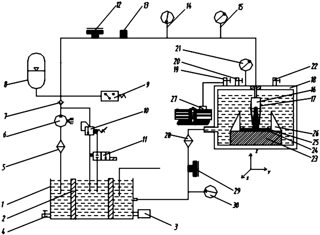
[0053] In conjunction with the accompanying drawings, a micro-part stamping and etching device based on high-pressure submerged cavitation water jet (taking stamping as an example, it includes the following steps:

[0054] (1) if Figure 5 As shown, the stamping die 25 is placed on the three-coordinate workbench 23, on which the micro-parts that need to be stamped are arranged, and the stamping die and the micro-parts are positioned and clamped by the positioning clamping device 26;

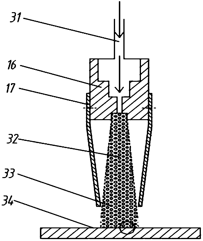
[0055] (2) Select a suitable cavitation water jet guide device 17 according to the shape to be stamped by the micro parts, and connect it with the cavitation nozzle 16 by screws; select a convergent guide device in this embodiment;

[0056] (3) Open the water inlet valve 22, so that the high-pressure vessel 18 is filled with water and the water surface exceeds the height d of the upper edge of the cavitation nozzle 16 1 =2cm, open the booster valve 19 and open the high-pressure air compressor 27...

Embodiment 2

[0065] A micro-part stamping and etching device based on high-pressure submerged cavitation water jet is described in detail in conjunction with the accompanying drawings. Taking etching processing as an example, it includes the following steps:

[0066] (1) if Figure 7 As shown, the micro-parts to be etched are placed on the three-coordinate workbench 23, and the etching mask 25 is arranged on it, and the etching mask and the micro-parts are positioned and clamped by the positioning clamping device 26;

[0067] (2) if Figure 7 As shown, according to the shape of the micro-parts to be etched, select a suitable cavitation water jet guide device 26, and connect it to the cavitation nozzle 16 through screws; in this embodiment, a convergent guide device is selected in the process of first etching the keyway;

[0068] (3) Open the water inlet valve 22, so that the high-pressure vessel 18 is filled with water and the water surface exceeds the height d of the upper edge of the cavi...


PUM

PropertyMeasurementUnit
thicknessaaaaaaaaaa

Abstract

The invention relates to a device and a method for stamping and etching a micro part based on high-pressure submerging and cavitating water jet. The method is characterized in that high-pressure impact wave, high-speed micro jet and local high temperature generated by cavitation collapse in high-pressure submerging and cavitating water jet are utilized, and a corresponding mould is combined to stamp or etch and process the micro part, so that a needed shape is formed by stamping or accumulative etching. A device used for generating high-pressure submerging and cavitating water jet comprises awater storage tank system, a metering pump-energy accumulator-unloading valve constant-pressure energy system, a cavitating water jet generating system, a high-pressure submerging and processing system, a circulating loop system and related peripheral equipment. Different from a conventional processing method, the method disclosed by the invention enriches the processing method for stamping and etching the micro part, so that stamping degree and precision, and etching and processing precision and efficiency are improved greatly; and the whole device is simple in structure, is easy to operate,is easy to maintain, is relatively low in cost, and is environmentally friendly.

Description

technical field [0001] The invention relates to the fields of mechanical manufacturing, material forming and special processing, in particular to a device and method for stamping and etching micro-parts based on high-pressure submerged cavitation water jets. Background technique [0002] In the industrial field, there are more and more applications for various micro components, especially in the fields of biology, environmental monitoring, aerospace, industry and defense. Due to changes in scale effects, structures, materials, and working principles, the forming and processing of micro-parts is becoming more and more difficult, including the difficulty of forming and processing brought about by the improvement of material properties, and the complexity brought about by the tiny structure of parts. For example, the strength of steel increases from 250MPa to 1000MPa, the plasticity decreases from 45% to 12%, the strength of aluminum alloy increases from 150MPa to 530MPa, and t...

Claims


Application Information

Patent Timeline
Patent Type & Authority Patents(China)
IPC IPC(8): B21D26/00B21D26/06B23D79/00
CPCB21D26/00B21D26/06B23D79/00
Inventor 李富柱谭中锐王匀于超蒋鹏赟姜鼎陆素雯蒋志刚
Owner JIANGSU UNIV
Learn More