
Heater heating element manufacturing method

A technology of heating element and manufacturing method, which is applied to electrical elements, ohmic resistance heating, electric heating devices, etc., to achieve the effects of compact structure, improved thermal conductivity, and convenient power control

Inactive Publication Date: 2017-12-08
ZHENJIANG HELMHOLTZ HEAT TRANSFER TRANS SYST CO LTD
View PDF3 Cites 3 Cited by
  • Summary
  • Abstract
  • Description
  • Claims
  • Application Information

AI Technical Summary

Problems solved by technology

[0003] In order to overcome the defects in the prior art, it is of great practical significance to develop a heater that does not change the resistance of the heating body due to changes in working temperature, so as to keep the heating power constant.

Method used


Image

  • Heater heating element manufacturing method
  • Heater heating element manufacturing method
  • Heater heating element manufacturing method

Examples


Embodiment 1

[0034] Embodiment 1, during the plasma spraying process, the nozzle and the electrode of the spray gun are respectively connected to the positive and negative poles of the power supply. Working gas (such as helium, nitrogen, etc.) is passed between the nozzle and the electrode, and the arc is ignited by high-frequency sparks. The arc heats the gas and ionizes it to generate high-temperature plasma gas. The powder feeding gas pipe sends the pre-sprayed powder material into the high-temperature plasma gas and is quickly heated to a molten state. The plasma flame flow is formed with nitrogen or argon as the carrier gas. Spray at a certain speed to the surface of the preheated substrate to form a dense coating. When spraying metal or metal alloy, a certain amount of hydrogen can be mixed in the carrier gas as a reducing gas to prevent the coating from being oxidized during the formation process.

Embodiment 2

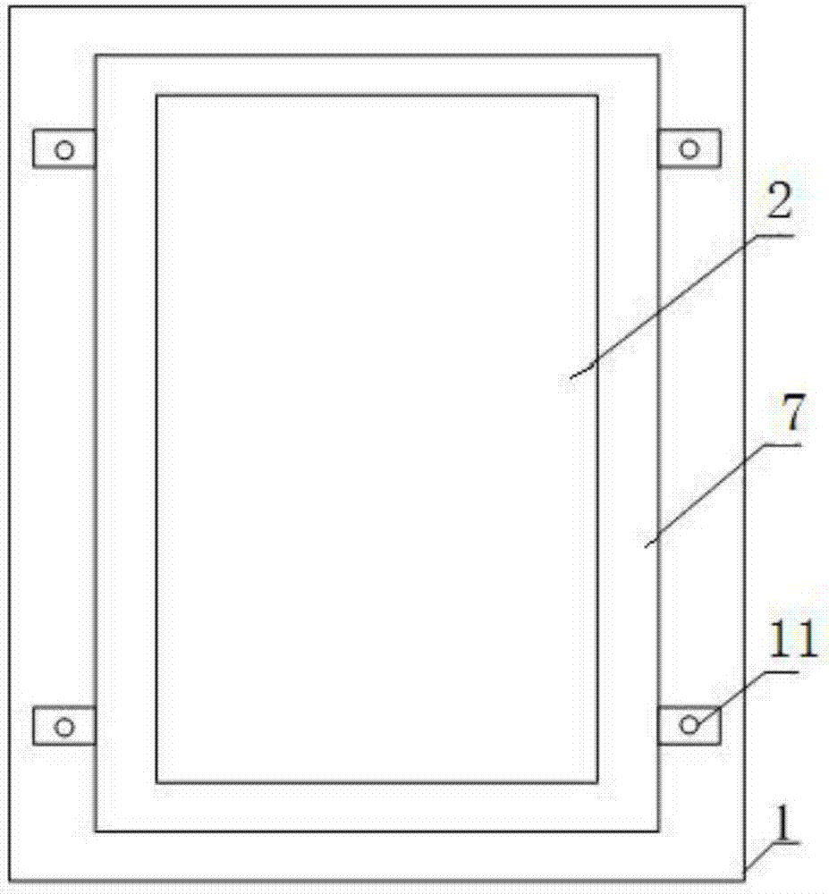
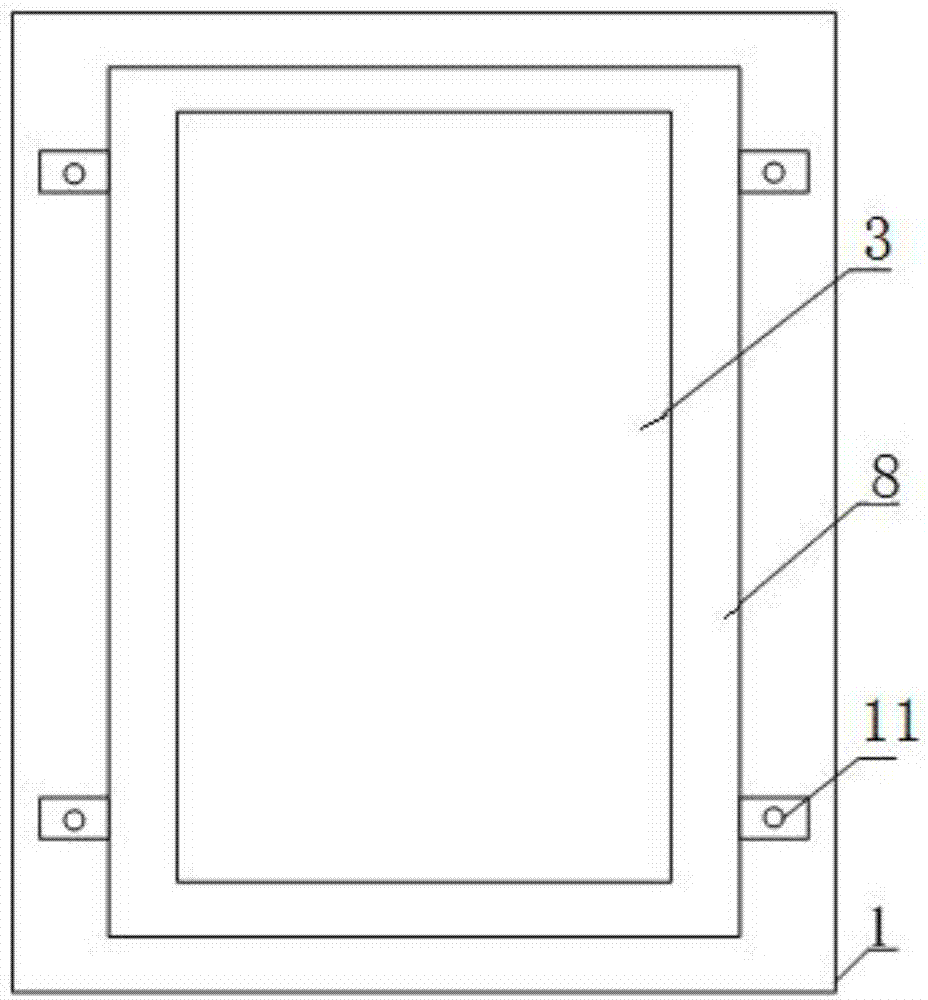
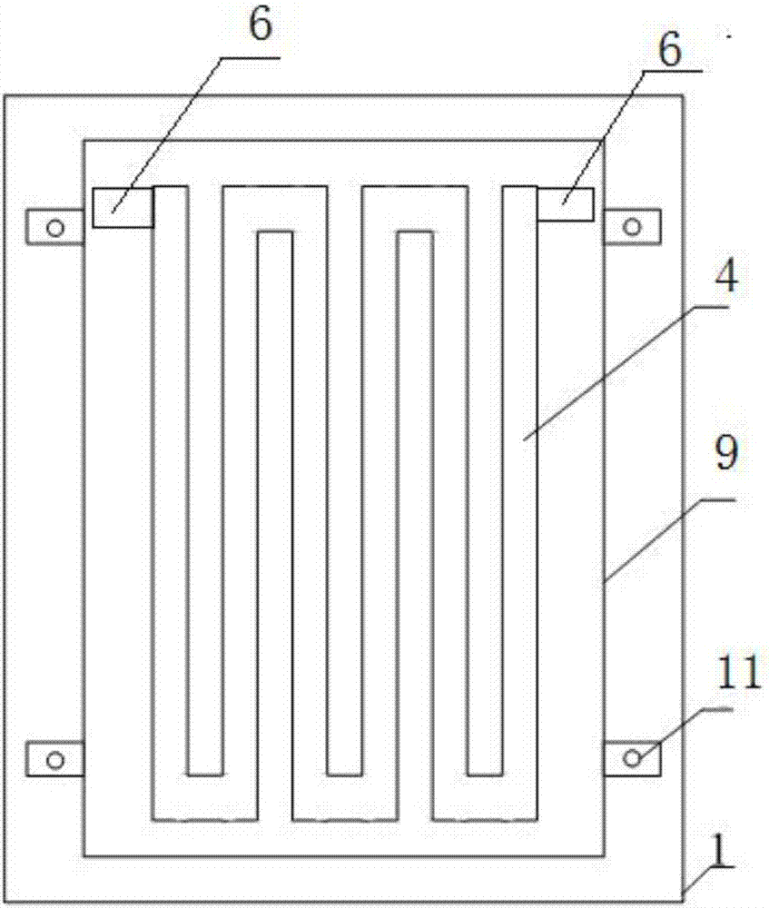
[0035] Embodiment 2, the heating layer 4 is sprayed on the first ceramic insulating layer 3 by a flame spraying method, and the flame spraying method includes the following steps:

[0036] The nickel-chromium alloy powder particles are injected into the flame through the powder feeding tube, and the flame heats the nickel-chromium alloy powder particles to a molten and semi-molten state;

[0037] Argon or nitrogen is used as the protective gas, and the nickel-chromium alloy powder particles are atomized by the protective gas flow, and sprayed onto the first ceramic insulating layer 3 at a speed of 2000m / s to form a dense heating layer 4 . Since the temperature of the molten and semi-molten state of nickel-chromium material has begun to drop before spraying reaches the alumina ceramic insulation layer, the temperature will drop in a large range when it reaches the spraying area of ​​the heater, so that the temperature of the heating area is low and the residual stress is small. ...


PUM

PropertyMeasurementUnit
diameteraaaaaaaaaa

Abstract

The invention discloses a heater heating element manufacturing method. The heater heating element manufacturing method comprises the steps that a heater shell is polished through a sand blasting process; a buffer layer tool is placed on a heating area and fixed, and through a hot spraying process, a buffer layer is sprayed on the heating area; a first ceramic insulation layer shield tool is placed on the buffer layer and fixed, and through the hot spraying process, an aluminum oxide ceramic material is sprayed on the buffer layer to form a first ceramic insulation layer; a heat layer shield tool is placed on the first ceramic insulation layer and fixed, and a heating layer is sprayed on the first ceramic insulation layer through the hot spraying process; heating element electrodes are sprayed at the two ends on the heating layer; and after spraying of the heating layer is completed, a second ceramic insulation layer shield tool is placed on the heating layer and fixed, and through the hot spraying process, an aluminum oxide ceramic material is sprayed to form a second ceramic insulation layer. According to the heater heating element manufacturing method, the heat conducting efficiency can be improved, and through the hot spraying process, heating elements are sprayed on the surface of the heat exchange surface of a heater to be used as heat emitting sources of the heater.

Description

technical field [0001] The invention relates to a heating element of a heater, in particular to a method for manufacturing the heating element of a heater. Background technique [0002] At present, most of the commonly used heater heating elements use PTC thermal elements, and the heating elements are generally bonded and welded to the heat exchanger. Due to the large thermal resistance of the bonding and welding materials, the heat conduction loss is large and the heating efficiency is low. Greatly reduced. And due to the inherent characteristics of the PTC resistor, at low temperature, the resistance of the PTC resistor is very small, that is to say, when the PTC heater is started, due to the small resistance of the PTC, it will bring a large surge current, which is harmful to the control circuit will have a greater impact. At high temperature, the resistance value of the PTC resistor is relatively large. Under the condition of a certain supply voltage, the output power ...

Claims


Application Information

Patent Timeline
Patent Type & Authority Applications(China)
IPC IPC(8): C23C4/073C23C4/08C23C4/11
CPCC23C4/073C23C4/08C23C4/11H05B2203/017
Inventor 单龙魏先玉蒋奕
Owner ZHENJIANG HELMHOLTZ HEAT TRANSFER TRANS SYST CO LTD
Learn More