
Method and system for identifying moment of inertia of permanent magnet synchronous motor

A permanent magnet synchronous motor and moment of inertia technology, applied in the field of system identification, can solve problems such as noise interference and inconvenient operation, and achieve the effects of improving accuracy, good stability, and improving user experience

Inactive Publication Date: 2017-09-15
GUANGDONG UNIV OF TECH
View PDF5 Cites 4 Cited by
  • Summary
  • Abstract
  • Description
  • Claims
  • Application Information

AI Technical Summary

Problems solved by technology

The direct calculation method is intuitive and practical, and is suitable for systems with a known rotor structure. It obtains the moment of inertia through the radius and mass of the rotor, but the actual operation is inconvenient
The least squares method is extremely susceptible to noise interference

Method used


Image

  • Method and system for identifying moment of inertia of permanent magnet synchronous motor
  • Method and system for identifying moment of inertia of permanent magnet synchronous motor
  • Method and system for identifying moment of inertia of permanent magnet synchronous motor

Examples


Embodiment Construction

[0034] In order to make the purpose, technical solutions and advantages of the embodiments of the present invention clearer, the technical solutions in the embodiments of the present invention will be clearly and completely described below in conjunction with the drawings in the embodiments of the present invention. Obviously, the described embodiments It is a part of embodiments of the present invention, but not all embodiments. Based on the embodiments of the present invention, all other embodiments obtained by persons of ordinary skill in the art without making creative efforts belong to the protection scope of the present invention.

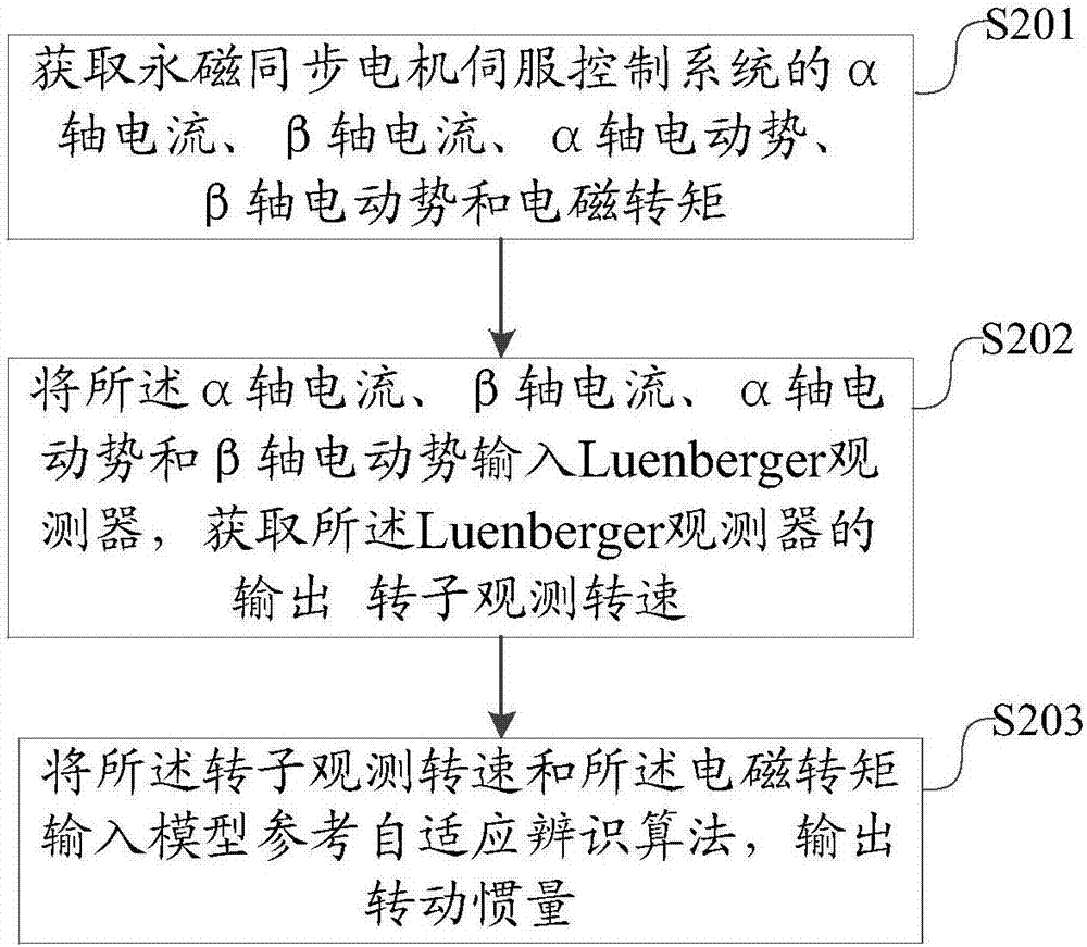
[0035] Please refer to figure 1 , figure 1 It is a flowchart of a method for identifying the moment of inertia of a permanent magnet synchronous motor provided by an embodiment of the present invention. The method can include:

[0036] Step 101: Obtain the α-axis current, β-axis current, α-axis electromotive force, β-axis electromotive for...


PUM


Abstract

The invention discloses a method and system for identifying the moment of inertia of a permanent magnet synchronous motor. The method comprises the following steps: obtaining alpha axis current, beta axis current, an alpha axis electromotive force, a beta axis electromotive force and an electromagnetic torque of a servo control system of the permanent magnet synchronous motor; inputting the alpha axis current, the beta axis current, the alpha axis electromotive force and the beta axis electromotive force into a speed observer, and obtaining an output rotor observation speed of the speed observer; and inputting the rotor observation speed and the electromagnetic torque into a model reference adaptive identification algorithm, and outputting the moment of inertia. According to the method disclosed by the invention, the output rotor observation speed of the speed observer and the obtained electromagnetic torque are used as the input of the model reference adaptive identification algorithm to obtain the moment of inertia, the speed observer can eliminate phase hysteresis caused by obtaining the speed through position and improve the identification accuracy, and the model reference adaptive identification algorithm can guarantee good stability for the identification system and improve the user experience.

Description

technical field [0001] The invention relates to the field of system identification, in particular to an identification method and system for the moment of inertia of a permanent magnet synchronous motor. Background technique [0002] Servo means "serving" and "obedience". The servo system is an automatic control system that accurately tracks or reproduces a given process. Variety. The DC servo system was once popular due to the advantages of easy control and good speed regulation. However, the structure of the brush and commutator of the DC servo motor is complex, and the commutation cremation makes it easy to wear and tear, and the motor needs to be maintained frequently. Therefore, the used The occasions are limited and cannot be used in flammable and explosive occasions. At the same time, there are also disadvantages such as large moment of inertia, slow response speed, large mechanical transmission ratio of the system, small heat capacity, and unsuitable for high-speed ...

Claims


Application Information

Patent Timeline
IPC IPC(8): H02P21/14
CPCH02P21/14
Inventor 赵友阳曾岳南唐彬彬徐道明杨昌铸
Owner GUANGDONG UNIV OF TECH
Learn More