Silicon-carbon composite, a method for preparing said composite, and an electrode material and a battery comprising said composite
A composite, silicon carbon technology, applied in battery electrodes, secondary batteries, circuits, etc., can solve problems such as low production efficiency and poor long-term cycle performance
- Summary
- Abstract
- Description
- Claims
- Application Information
AI Technical Summary
Problems solved by technology
Method used
Image
Examples
Embodiment 1
[0070] First, 0.73 g of Si NPs (50–200 nm in size, Alfa-Aesar), 0.11 g of CNTs (10–20 nm in OD, 10–30 μm in length, Chengdu Organic Chemical Co., Ltd.) and 0.37 g of PF (Shandong Shengquan Shenquan Group ) was dispersed in 150mL absolute ethanol, stirred and ultrasonically treated for 1 hour. Second, the mixture was spray-dried (inlet temperature: 170 °C; outlet temperature: 100 °C) to form PF-wrapped Si NP and CNT (Si / CNT@PF) composite microparticles. Finally, the obtained Si / CNT@PF composite was heated in an argon atmosphere at 5 °C / min to 900 °C for 2 h, and PF was pyrolyzed into amorphous carbon. The resulting composite is Si / CNT@C. Since the residual carbon fraction of PF is 58%, the weight ratio of Si NP:CNT:C coating in the Si / CNT@C composite was calculated to be 69:10:21.
[0071] structural assessment :
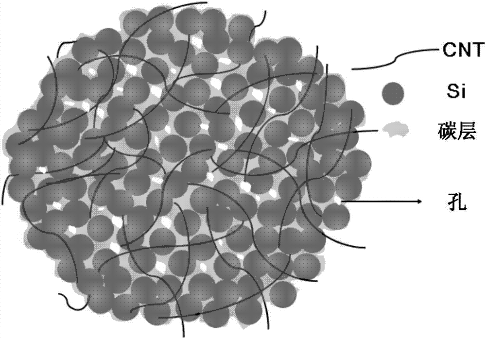
[0072] figure 1 A schematic sketch of Si / CNT@C is shown. The structure of Si / CNT@C can be described as follows: micron-sized spheres consist of nanometer-size...
Embodiment 2
[0090] Example 2 was carried out similarly to Example 1, with the difference that the weight ratio of SiNP:CNT:C coating in the resulting Si / CNT@C composite was calculated to be 54:10:36.
[0091] Figure 9 Shown is (b) the cycle performance of Si / CNT@C of Example 2.
Embodiment 3
[0093] Example 3 is implemented similarly to Example 1, the difference is that copper ethyl acetoacetate (Cu salt) is additionally dispersed in absolute ethanol as a copper source, and the intermediate product of step 2) is Si NP+CNT wrapped by PF + Cu salt (Si / CNT / Cu salt@PF), the calculated weight ratio of Si NP:CNT:Cu:C coating in the resulting composite (Si / CNT / Cu@C) is 60:10:10 :20.
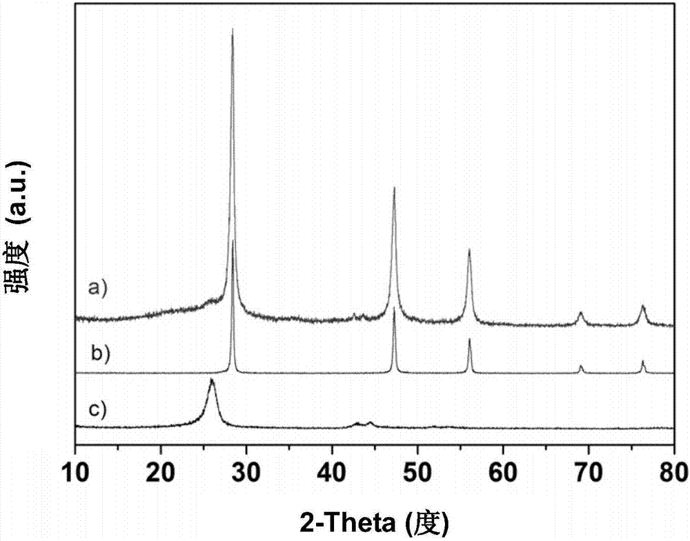
[0094] Figure 9 Shown is the cycle performance of Si / CNT / Cu@C of (c) embodiment 3; Figure 10 Shown are the SEM photos of (a) Si / CNT / Cu salt @PF and (b) Si / CNT / Cu@C of Example 3; Figure 11 Shown is (a) the XRD spectrum of Si / CNT / Cu@C of Example 3.
[0095] Depend on Figure 9 It can be seen that the cycle performance of the Si / CNT / Cu@C composite of Example 3 is further improved by adding copper.
PUM
| Property | Measurement | Unit |
|---|---|---|
| Pore volume | aaaaa | aaaaa |
| Aperture | aaaaa | aaaaa |
| Specific surface area | aaaaa | aaaaa |
Abstract
Description
Claims
Application Information
 - R&D
- Intellectual Property
- Life Sciences
- Materials
- Tech Scout
- Unparalleled Data Quality
- Higher Quality Content
- 60% Fewer Hallucinations
Browse by: Latest US Patents, China's latest patents, Technical Efficacy Thesaurus, Application Domain, Technology Topic, Popular Technical Reports.
© 2025 PatSnap. All rights reserved.Legal|Privacy policy|Modern Slavery Act Transparency Statement|Sitemap|About US| Contact US: help@patsnap.com


