
Low trigger voltage SCR structure based on floating trap trigger

A low trigger voltage, floating technology, applied in the direction of circuits, electrical components, electric solid devices, etc., can solve problems such as excessive trigger voltage

Active Publication Date: 2017-08-04
UNIV OF ELECTRONICS SCI & TECH OF CHINA
View PDF3 Cites 14 Cited by
  • Summary
  • Abstract
  • Description
  • Claims
  • Application Information

AI Technical Summary

Problems solved by technology

Therefore, the trigger voltage of the LVTSCR device is determined by the drain-source breakdown voltage BV of the P-channel MOSFET device DS decision; the trigger voltage is still too high for a low-voltage process

Method used


Image

  • Low trigger voltage SCR structure based on floating trap trigger
  • Low trigger voltage SCR structure based on floating trap trigger
  • Low trigger voltage SCR structure based on floating trap trigger

Examples


Embodiment Construction

[0026] The present invention will be described in detail below in conjunction with the accompanying drawings and specific embodiments.

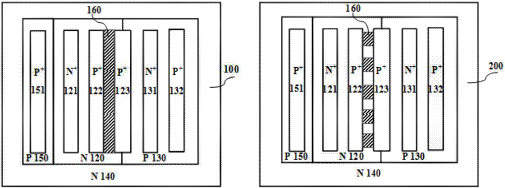
[0027] This embodiment provides a low trigger voltage SCR structure based on floating well trigger, such as figure 1 As shown, its structure includes:

[0028] p-type silicon substrate 110;

[0029] An n-type deep well region 140 is formed on the substrate 110;

[0030] An adjacent n-type well region 120 and a p-type well region 130 are formed on the n-type deep well region 140;

[0031] An n-type heavily doped region 121 and a p-type heavily doped region 122 are provided in the n-type well region 120, and the regions 121 and 122 are connected to the anode;

[0032] The p-type well region 130 is provided with an n-type heavily doped region 131 and a p-type heavily doped region 132, and the regions 131 and 132 are connected to the cathode;

[0033] A p-type heavily doped region 123 is bridged between the n-type well region 120 and the p-t...


PUM


Abstract

The invention belongs to the electrostatic discharge protection field of an integrated circuit and especially provides a low trigger voltage SCR structure based on floating trap trigger used for ESD protection. And the structure is used for further reducing a trigger voltage of a LVTSCR device. Through an internal structure design, one floating trap structure is introduced into the device. The floating trap structure is equivalent to one diode structure, an anode is connected to a polycrystalline silicon grid electrode of a PMOS and a cathode is connected to an anode of a SCR. When an ESD pulse is coming, a potential of a floating trap is lower than an anode potential of a SCR device. A potential difference between the two is enough to make the PMOS be started. After a P channel MOSFET is started, a parasitic NPN transistor in the SCR device is triggered to be started, then a parasitic PNP transistor is triggered to be started, and finally the SCR device starts and discharges an ESD current. Therefore, a trigger voltage of the device is determined by the floating trap structure and a parasitic PMOS grid source capacitor so that a purpose of reducing a SCR device trigger voltage can be realized and the trigger voltage can be modulated.

Description

technical field [0001] The invention belongs to the field of electrostatic discharge (ESD: Electro-Static discharge) protection of integrated circuits, relates to an ESD protection structure device, in particular to a new silicon-controlled rectifier (SCR: Semiconductor Control Rectifier) ​​with low trigger voltage for ESD protection ) device structure. Background technique [0002] Electrostatic discharge is one of the important branches of integrated circuit reliability. From chip manufacturing to production assembly, from product transportation to daily use, electrostatic discharge is accompanied by the occurrence of electrostatic discharge during the entire life cycle of electronic products. According to statistics, more than one-third of electronic product failures are caused by ESD / EOS problems. Considering such a large quantity, designing ESD protection devices with superior performance has attracted more and more attention. [0003] In order to achieve the purpose ...

Claims


Application Information

Patent Timeline
IPC IPC(8): H01L27/02H01L23/60H01L29/06
CPCH01L23/60H01L27/0248H01L27/0266H01L29/0611H01L29/0688
Inventor 刘继芝钱玲莉刘志伟
Owner UNIV OF ELECTRONICS SCI & TECH OF CHINA
Learn More