
Graphene-coated silicon nanoparticle with novel structure, and preparation method thereof

A technology coated with silicon nanoparticles and graphene, which is applied to structural parts, electrical components, electrochemical generators, etc., can solve the problems of slow electron transfer rate, pollution of the environment by waste liquid containing Cu ions, and separation of active material particles and current collectors. and other issues, to achieve high-rate charge-discharge performance and safety performance, to facilitate large-scale production, and to reduce the effect of battery volume changes

Inactive Publication Date: 2017-06-23
SHANGHAI SHANSHAN TECH CO LTD
View PDF8 Cites 29 Cited by
  • Summary
  • Abstract
  • Description
  • Claims
  • Application Information

AI Technical Summary

Problems solved by technology

[0002] With the development of portable mobile devices and electric vehicles, people's demand for energy storage devices with higher energy density and higher power density is becoming more and more urgent. Lithium-ion batteries (372mAh / g) with graphite as the negative electrode can no longer meet consumer demand. , therefore, it is imminent to find anode materials with higher capacity
Because of its ultra-high theoretical lithium storage capacity (4200mAh / g) and abundant resources, silicon materials are considered to have the most potential to become the anode material of a new generation of lithium-ion batteries. However, silicon materials still have the following problems in the application of anode materials. Problems to be solved urgently: 1. As a semiconductor material, silicon has poor conductivity and slow electron migration rate. When it is used as the negative electrode material of lithium-ion batteries, the rate performance will inevitably be reduced; 2. During the charging and discharging process, due to the intercalation of lithium ions / de-intercalation, resulting in a change in the volume of the silicon material (volume expansion rate of more than 300%). This repeated volume change will inevitably lead to the collapse of the internal structure of the active material particles, reduce the contact between the active material particles, and cause the active material particles and the current collector. Detachment will eventually cause a series of problems such as capacity fading, rate performance reduction, and safety; 3. Unstable active material particle surface causes excessive formation of SEI, resulting in irreversible capacity loss
The composite material has high capacity and good cycle performance, but the preparation conditions are not easy to control, high energy consumption, difficult to batch production, and the resulting waste liquid containing Cu ions pollutes the environment

Method used


Image

  • Graphene-coated silicon nanoparticle with novel structure, and preparation method thereof
  • Graphene-coated silicon nanoparticle with novel structure, and preparation method thereof
  • Graphene-coated silicon nanoparticle with novel structure, and preparation method thereof

Examples


Embodiment 1

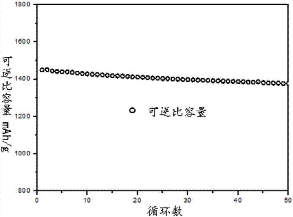
[0030] see figure 1 , the preparation method of novel structure graphene-coated silicon nanoparticles adopts the following preparation steps:

[0031] Material preparation: Take bulk commercial silicon and 6mm grinding balls, mix them at a ball-to-material ratio of 15:1, ball mill for 7 hours at a speed of 400r / min, sieve out the powder and use a Malvern 3000 laser particle size analysis The particle size range of the material tested by the instrument is obtained through testing. The particle size of the prepared silicon powder is in the range of 0.5-20.0um.

[0032] Step 1. Surface oxidation: Put the prepared silicon powder into a quartz crucible and put it into a high-temperature furnace. After gradually raising the temperature to 900°C, start to introduce compressed air and keep it warm for 1 hour. After cooling, the surface oxidized silicon powder is obtained. The oxygen content was tested by heating inert gas fusion-infrared absorption method, and the oxygen content was ...

Embodiment 2

[0041] The material preparation conditions are as in Example 1, the difference is that the silicon powder used is obtained by ball milling for 4 hours, and the particle size range of the material is tested using a Malvern 3000 laser particle size analyzer. The obtained silicon powder has a particle size of 0.6 -50um range.

[0042] The same method as in Example 1 was used to perform electrochemical tests and compare the volume expansion effect of the materials.

Embodiment 3

[0044] The material preparation conditions are the same as in Example 1, except that the oxidation time of the silicon powder is 0.5 h, and the oxygen content is 28.3% as measured by the pulse heating inert gas melting-infrared absorption method.

[0045] The same method as in Example 1 was used to perform electrochemical tests and compare the volume expansion effect of the materials.


PUM

PropertyMeasurementUnit
Concentrationaaaaaaaaaa
Particle sizeaaaaaaaaaa
Concentrationaaaaaaaaaa

Abstract

The invention relates to the field of lithium ion battery electrode materials, in particular to a graphene-coated silicon nanoparticle with a novel structure, and a preparation method thereof. The graphene-coated silicon nanoparticle is characterized by being formed by a reduced graphene oxide / carbon shell coating an outer layer, a silicon nanoparticle core located in the reduced graphene oxide / carbon shell, and a cavity layer between the reduced graphene oxide / carbon shell and the silicon nanoparticle core. Compared with the prior art, according to the graphene-coated silicon nanoparticle provided by the invention, the thickness of a surface oxidation layer of a silicon particle is easy to control; surface oxidation silicon powder is dispersed in a solvent easily, and hydroxy on the surface of the particle enables the particle to be combined with a modifier easily; graphene coating the particle surface helps increase electric contact between particles as well as between the particle and a current collector, and is beneficial for electron transfer in a composite material to reduce impedance; carbon produced through high-temperature pyrolyzing of a modifier carbon chain and graphene jointly form a shell with a certain strength, and a stable SEI can be formed favorably.

Description

technical field [0001] The invention relates to the field of lithium-ion battery electrode materials, in particular to a novel structure graphene-coated silicon nanoparticle and a preparation method thereof. Background technique [0002] With the development of portable mobile devices and electric vehicles, people's demand for energy storage devices with higher energy density and higher power density is becoming more and more urgent. Lithium-ion batteries (372mAh / g) with graphite as the negative electrode can no longer meet consumer demand. , therefore, it is imminent to find anode materials with higher capacity. Because of its ultra-high theoretical lithium storage capacity (4200mAh / g) and abundant resources, silicon materials are considered to have the most potential to become the anode material of a new generation of lithium-ion batteries. However, silicon materials still have the following problems in the application of anode materials. Problems to be solved urgently: 1...

Claims


Application Information

Patent Timeline
IPC IPC(8): H01M4/36H01M4/38H01M4/62H01M10/0525
CPCH01M4/366H01M4/386H01M4/62H01M4/625H01M4/628H01M10/0525Y02E60/10
Inventor 童磊余德馨郑安华杜辉玉郑远辉
Owner SHANGHAI SHANSHAN TECH CO LTD
Learn More