
Magnesium ferrite-based magnetic dielectric material and preparation method therefor

A technology of magnesium ferrite and magnetic medium, which is applied in the field of magnesium ferrite-based magnetic medium materials and its preparation, can solve the problems of affecting antenna performance, limiting antenna size, high magnetic permeability and permittivity, and improving radiation Efficiency and bandwidth, miniaturization, and low dielectric properties

Active Publication Date: 2017-04-26
UNIV OF ELECTRONICS SCI & TECH OF CHINA
View PDF2 Cites 4 Cited by
  • Summary
  • Abstract
  • Description
  • Claims
  • Application Information

AI Technical Summary

Problems solved by technology

Su Hua and Tang Xiaoli of the University of Electronic Science and Technology of China applied for a Chinese invention patent "a low-frequency microstrip antenna substrate material and its preparation method (application number 200910058209.3)" in 2009, and proposed a spinel ferrite and strontium bismuth titanate Ceramic composite and other magnetic dielectric materials, but the magnetic permeability and permittivity of the magnetic dielectric material are high, which limits the size of the antenna
Tang Xiaoli, Su Hua and others applied for the Chinese invention patent "A Microstrip Antenna Composite Substrate (Application No. 201110235563.5)" in 2012, and proposed a Co 2 Z barium strontium ferrite material and polypropylene resin material are composited and other magnetic dielectric materials, but the polypropylene resin organic matter used in the magnetic dielectric material is greatly affected by temperature in practical applications, which seriously affects the performance of the antenna

Method used


Image

  • Magnesium ferrite-based magnetic dielectric material and preparation method therefor
  • Magnesium ferrite-based magnetic dielectric material and preparation method therefor
  • Magnesium ferrite-based magnetic dielectric material and preparation method therefor

Examples


Embodiment 1

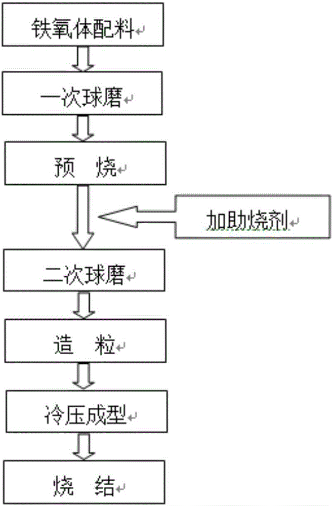
[0021] A method for preparing a magnesium ferrite-based magnetic dielectric material, comprising the following steps:

[0022] Step 1: Magnesium oxide (MgO), cadmium oxide (CdO) and iron oxide (Fe 2 o 3 ) as raw material, according to the main phase material Mg 1- x Cd x Fe 2 o 4 The proportion of metal elements in (x=0.1) is converted to MgO, CdO and Fe 2 o 3 After weighing 7.2g of magnesium oxide, 2.56g of cadmium oxide, and 32.0g of iron oxide, they were wet-milled in a planetary ball mill for 18 hours at a speed of 220 rpm, and the ball-milling medium was deionized water;

[0023] Step 2: Sieve the primary ball mill drying material obtained in step 1 and compact it in a sintered crucible, raise the heating rate to the pre-burning temperature at a rate of 2°C / min for pre-burning, and naturally cool to room temperature with the furnace to obtain ferrite Pre-burn the powder; the pre-fire temperature is 1050°C, and the holding time is 4h;

[0024] Step 3: Add 2.0gBi t...

Embodiment 2

[0029] A method for preparing a magnesium ferrite-based magnetic dielectric material, comprising the following steps:

[0030] Step 1: Magnesium oxide (MgO), cadmium oxide (CdO) and iron oxide (Fe 2 o 3 ) as raw material, according to the main phase material Mg 1- x Cd x Fe 2 o 4 The proportion of metal elements in (x=0.2) is converted to MgO, CdO and Fe 2 o 3 After weighing 6.4g of magnesium oxide, 5.12g of cadmium oxide, and 32.0g of iron oxide, they were wet-milled in a planetary ball mill for 18 hours at a speed of 220 rpm, and the ball-milling medium was deionized water;

[0031] Step 2: Sieve the primary ball mill drying material obtained in step 1 and compact it in a sintered crucible, raise the heating rate to the pre-burning temperature at a rate of 2°C / min for pre-burning, and naturally cool to room temperature with the furnace to obtain ferrite Pre-burn the powder; the pre-fire temperature is 1100°C, and the holding time is 4h;

[0032] Step 3: Add 2.17g Bi...

Embodiment 3

[0037] A method for preparing a magnesium ferrite-based magnetic dielectric material, comprising the following steps:

[0038] Step 1: Magnesium oxide (MgO), cadmium oxide (CdO) and iron oxide (Fe 2 o 3 ) as raw material, according to the main phase material Mg 1- x Cd x Fe 2 o 4 The proportion of metal elements in (x=0.3) is converted to MgO, CdO and Fe 2 o 3 After weighing 5.6g of magnesium oxide, 7.68g of cadmium oxide, and 32.0g of iron oxide, they were wet-milled in a planetary ball mill for 18 hours at a speed of 220 rpm, and the ball-milling medium was deionized water;

[0039] Step 2: Sieve the primary ball mill drying material obtained in step 1 and compact it in a sintered crucible, raise the heating rate to the pre-burning temperature at a rate of 2°C / min for pre-burning, and naturally cool to room temperature with the furnace to obtain ferrite Pre-burn the powder; the pre-fire temperature is 1100°C, and the holding time is 4h;

[0040] Step 3: Add 2.26g Bi...


PUM


Abstract

The invention discloses a magnesium ferrite-based magnetic dielectric material and a preparation method therefor, and belongs to the field of an electronic material. The magnesium ferrite-based magnetic dielectric material consists of a main phase material and an auxiliary phase material at a mass percentage ratio of 100 to (2-20) in a compounding manner, wherein the main phase material is Mg<1-x>Cd<x>Fe<2>O<4> spinel ferrite, x is equal to 0.1-0.3, and the auxiliary phase material is Bi<2>O<3>; and performing ball milling and mixing on the main phase material and the auxiliary phase material, and then carrying out drying, sieving, palletizing, pressing and shaping, and next, sintering at a temperature of 880-960 DEG C for 1-6h. The magnetic dielectric material disclosed by the invention realizes low-temperature sintering and magnetic dielectric approximate equality, and has equal magnetic dielectric property and low loss property at a frequency range of 0.1-10MHz; and when the magnetic dielectric material is used as an antenna substrate material, miniaturization of an antenna can be well realized, and the radiation efficiency and bandwidth of a microstrip antenna can be improved, so that a new scheme is provided for design of small-dimensional wireless communication equipment.

Description

technical field [0001] The invention belongs to the field of electronic materials, and in particular relates to a magnesium ferrite-based magnetic dielectric material and a preparation method thereof. Background technique [0002] With the continuous development of miniaturization and integration of communication equipment, how to realize the miniaturization of antenna has become the research focus of researchers. According to the calculation formula of the antenna structure size, the structure size of the antenna is proportional to the wavelength of the wave in the medium. Therefore, when the traditional dielectric material substrate is used to process the lower frequency antenna, the size of the antenna is relatively small due to the low dielectric constant of the substrate. Large, can not meet the application in small communication equipment. [0003] In order to reduce the size, mass and volume of the microstrip antenna in the lower frequency band, according to the reso...

Claims


Application Information

Patent Timeline
Patent Type & Authority Applications(China)
IPC IPC(8): C04B35/26C04B35/622C04B35/64H01Q1/38
CPCC04B35/2683C04B35/622C04B35/64C04B2235/3206C04B2235/3241C04B2235/3272C04B2235/3298H01Q1/38
Inventor 李强李颉包生祥甘功雯李元勋张怀武
Owner UNIV OF ELECTRONICS SCI & TECH OF CHINA
Learn More