Scintillation event position determination in a radiation particle detector

一种辐射粒子、探测器的技术,应用在核成像系统,单光子发射计算机断层摄影扫描器领域,能够解决恶化闪烁事件定位等问题

Inactive Publication Date: 2017-02-22
KONINKLJIJKE PHILIPS NV
View PDF7 Cites 17 Cited by
  • Summary
  • Abstract
  • Description
  • Claims
  • Application Information

AI Technical Summary

Problems solved by technology

However, maximum likelihood methods are known to fail when information from multiple light sensors is lost, leading to degraded scintillation event localization

Method used


Image

  • Scintillation event position determination in a radiation particle detector
  • Scintillation event position determination in a radiation particle detector
  • Scintillation event position determination in a radiation particle detector

Examples


Embodiment Construction

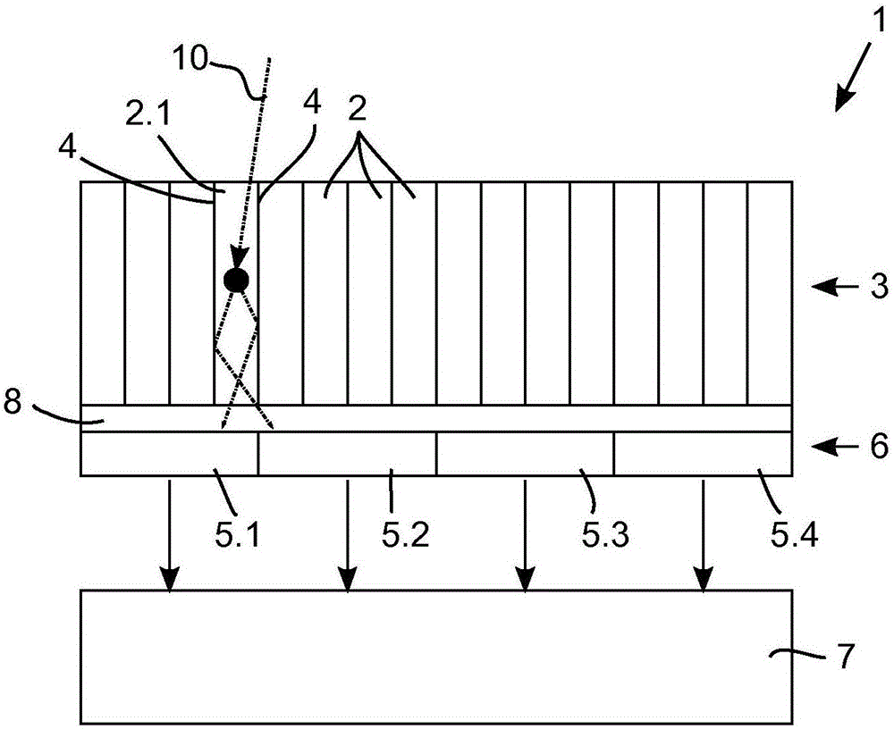
[0050] figure 1 A first embodiment of a radiation particle detector 1 for use in a nuclear imaging system (eg a high resolution PET scanner) is illustrated. The radiation particle detector 1 comprises a pixelated scintillator with a plurality of scintillator element locations, wherein the scintillator element locations are scintillator elements 2 . The material of the scintillator element 2 is chosen to provide a high stopping power of 511 keV gamma rays with a fast time delay of the scintillation burst. Some suitable scintillator materials are lutetium silicate (LSO), lutetium yttrium silicate (LYSO), and lanthanum bromide (LaBr). It should be appreciated that scintillator elements 2 made of other materials could be used instead. The structure of the scintillator material can be, for example, crystalline, polycrystalline or ceramic. The scintillator elements 2 are arranged in a scintillator layer 3 . In order to avoid light sharing between scintillator elements 2 , a refl...


PUM


Abstract

A method for determining the position of a scintillation event in a radiation particle detector with multiple scintillator element locations which are configured to emit a burst of photons responsive to a radiation particle being absorbed at the scintillator element location and with a plurality of photosensors (5.1, 5.2, 5.3, 5.4) optically coupled to said scintillator element locations, comprising the steps of determining, for each of the photosensors (5.1, 5.2, 5.3, 5.4), a triggering probability indicative of the probability of said photosensor (5.1, 5.2, 5.3, 5.4) measuring a number of photons that exceeds a predetermined triggering threshold; measuring a photon distribution with the photosensors (5.1, 5.2, 5.3, 5.4) indicative of the number of photons incident on the individual photosensors (5.1, 5.2, 5.3, 5.4); calculating, for each of the scintillator element locations, a likelihood that a scintillation event with a predetermined energy value took place in said scintillator element location based on the measured photon distribution and the triggering probability of each of the photosensors (5.1, 5.2, 5.3, 5.4); and identifying the scintillator element location having the maximum likelihood.

Description

technical field [0001] The invention relates to the field of radiation particle detectors. The invention finds particular application in nuclear imaging systems, such as positron emission tomography (PET) scanners for clinical or exploratory studies, and single photon emission computed tomography (SPECT) scanners. Background technique [0002] In PET scanners, pixelated scintillator elements are typically used to convert incident radiation particles into bursts of photons with wavelengths in the UV or visible spectrum. The scintillator elements are typically arranged in a matrix, wherein each scintillator element has approximately 1x1mm 2 to 4x4mm 2 base area. Scintillation events are detected by a photosensor coupled to the scintillator element. State-of-the-art PET scanners use solid-state light sensors, such as silicon photomultipliers (SiPMs), which typically include arrays of single-photon avalanche diodes (SPADs) configured to break down in response to the impact o...

Claims


Application Information

Patent Timeline
Patent Type & Authority Applications(China)
IPC IPC(8): G01T1/164
CPCG01T1/1647G01R33/481G01T1/1603G01T1/1642G01T1/20G01T1/243G01T1/2985
Inventor Y·贝尔克V·舒尔茨
Owner KONINKLJIJKE PHILIPS NV
Why Eureka
Try Eureka