
Lithium supplementing method for energy storage device

A technology for replenishing lithium and devices, applied in the manufacture of electrical components, electrochemical generators, hybrid/electric double layer capacitors, etc. Lithium cost, effect from wide sources

Inactive Publication Date: 2017-02-22
CENT SOUTH UNIV
View PDF16 Cites 28 Cited by
  • Summary
  • Abstract
  • Description
  • Claims
  • Application Information

AI Technical Summary

Problems solved by technology

These pre-intercalated lithium methods all have the following problems: (1) the chemical properties of lithium foil are extremely active, which has high requirements on the production process environment, which increases the complexity of the manufacturing process; (2) lithium metal exists in the device to occupy a certain volume, reducing the The energy density of the device; (3) lithium metal cannot be completely consumed, and remaining in the device will increase safety hazards
However, the production of stable lithium powder is difficult, costly and low in output, which limits its large-scale commercial application
In addition, the stable lithium powder supplements lithium by forming a micro-primary battery. During the lithium supplementation process, the lithium intercalation current of each part of the electrode is uncontrollable and uneven, and the lithium supplementation process occurs after the electrolyte is injected and prior to the battery formation process. Therefore, the lithium powder Lithium supplementation will seriously affect the SEI film structure of the battery, and ultimately reduce the stability and consistency of the battery

Method used


Image

  • Lithium supplementing method for energy storage device
  • Lithium supplementing method for energy storage device
  • Lithium supplementing method for energy storage device

Examples


Embodiment 1

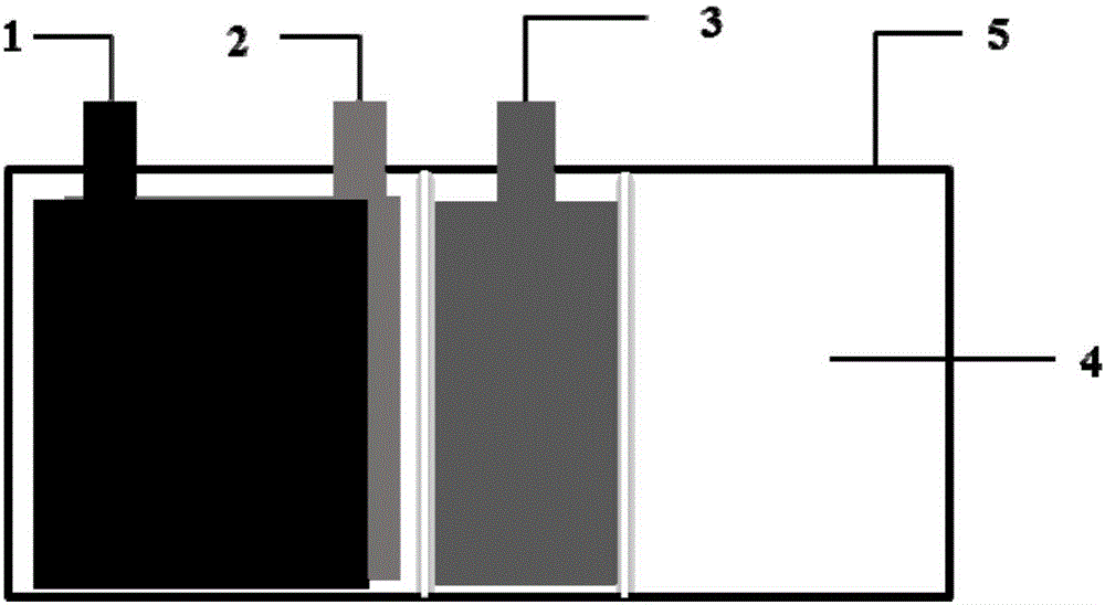
[0059] The aluminum plastic film was die-cut into a battery case with three chambers, and the LiCoO 2 The positive electrode and the graphite negative electrode are assembled into a core package, using LiCoO 2 The waste electrode sheet is a supplementary lithium electrode, and the through porosity of the positive and negative current collectors is 0%. The core pack and the lithium supplementing electrode are respectively placed in the core pack chamber and its adjacent chamber, and the airbag is adjacent to the lithium supplementing electrode. After the electrolyte is injected, the casing is encapsulated as a whole (one-time packaging), so that the chamber where the core pack and the lithium-replenishing electrode are located is rich in electrolyte. The battery structure is as follows: figure 1 shown.

[0060] After the battery core pack is formed, the lithium supplementary electrode is used as the anode, and the graphite negative electrode in the core pack is used as the ca...

Embodiment 2

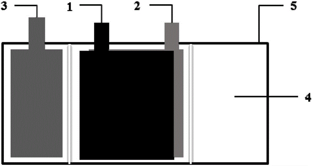
[0062] The aluminum plastic film was punched into a battery case with three chambers, and the LiNi 0.6 Mn 0.2 Co 0.2 O 2 The positive electrode and the Si / C negative electrode are assembled into a core package, using LiNi 0.5 Mn 0.3 Co 0.2 O 2 The waste electrode sheet is a supplementary lithium electrode, and the through porosity of the positive and negative current collectors is 15%. The core pack and the lithium supplementing electrode are respectively placed in the core pack chamber and its adjacent chamber, and the airbag is adjacent to the core pack chamber. After the electrolyte is injected, the casing is encapsulated as a whole (one-time packaging), so that the chamber where the core pack and the lithium-replenishing electrode are located is rich in electrolyte. The battery structure is as follows: figure 2 shown.

[0063] After the battery core pack is formed, the lithium supplement electrode is used as the anode, and the Si / C composite negative electrode in ...

Embodiment 3

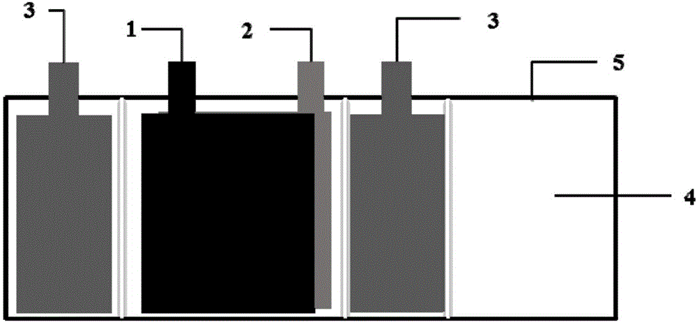
[0065] The aluminum plastic film was punched into a battery case with 4 chambers, and the LiNi 0.8 Mn 0.1 Co 0.1 O 2 The positive electrode and the Si / C composite negative electrode are assembled into a core package with LiMnO 4 with LiNi 0.6 Mn 0.2 Co 0.2 O 2 The mixed negative electrode sheet is a lithium supplementing electrode, and the number of lithium supplementing electrodes is 2, and the through porosity of the positive and negative current collectors is 30%. The core pack is placed in the core pack chamber, and the two lithium-replenishing electrodes are placed in the chambers on both sides of the core pack. Rich in electrolyte, battery structure such as image 3 shown.

[0066]After the battery core pack is formed, the lithium supplementary electrode is used as the anode, and the Si / C composite negative electrode in the core pack is used as the cathode. The amount is about 30% of the designed capacity of the Si / C composite anode. After the lithium suppleme...


PUM


Abstract

The invention relates to a lithium supplementing method for an energy storage device. The lithium supplementing method comprises the steps of adopting a device shell which consists of a cavity for placing a core pack, and m other cavities; putting the core pack and a lithium supplementing electrode into the core pack cavity and another cavity respectively, and injecting an electrolyte to enable the cavities where the core pack and the lithium supplementing electrode are located to be rich in electrolyte; performing formation treatment on the core pack, and then performing electrochemical lithium intercalation to obtain an A; or performing electrochemical lithium intercalation firstly, and then performing formation treatment on the core pack to obtain a B; after obtaining the A and B, performing n times of charge-discharge cycling treatment on the obtained A and B, next, extracting gas and redundant electrolyte from the core pack cavity, and sealing connection channels between the core pack cavity and other cavities to obtain a C; and finally, performing cavity-removing treatment on the obtained C to obtain a D, and performing machining and shaping on the D to obtain the finished energy storage device. The lithium supplementing method is simple and convenient to operate without greatly improving the production process of the existing lithium battery, and meanwhile, continuous production can be realized quite easily; and in addition, the lithium supplementing method is remarkable in effect and convenient to realize large-scale industrial application.

Description

technical field [0001] The invention belongs to the field of energy storage devices, and in particular relates to a method for replenishing lithium by an energy storage device. The energy storage device includes a lithium-ion battery, a lithium-sulfur battery, a lithium-ion capacitor, and a lithium-ion battery without a lithium source. Background technique [0002] Lithium-ion batteries have become one of the most widely used secondary batteries due to their advantages of high voltage, high energy density and long cycle life. However, with the miniaturization of portable electronic devices and the continuous development of long standby time, as well as the use of high-power and high-energy devices such as electric bicycles and electric vehicles, the energy density of lithium-ion batteries as energy storage power sources has been increasingly raised. high demands. In lithium-ion batteries currently using graphite as the negative electrode, Li + Both come from the positive e...

Claims


Application Information

Patent Timeline
IPC IPC(8): H01M10/058H01M10/0525H01M10/42H01G11/84
CPCH01G11/84H01M10/0525H01M10/058H01M10/4235Y02E60/10Y02P70/50
Inventor 洪波赖延清闫霄林张治安张凯李劼
Owner CENT SOUTH UNIV
Learn More