Vibration diaphragm in MEMS microphone, and MEMS microphone
A microphone and combined technology, applied in the directions of plane diaphragm, diaphragm fixing/tightening, diaphragm structure, etc., can solve problems such as diaphragm rupture and damage, microphone failure, etc., to meet performance requirements and avoid damage Effect
- Summary
- Abstract
- Description
- Claims
- Application Information
AI Technical Summary
Problems solved by technology
Method used
Image

Examples
Embodiment 1
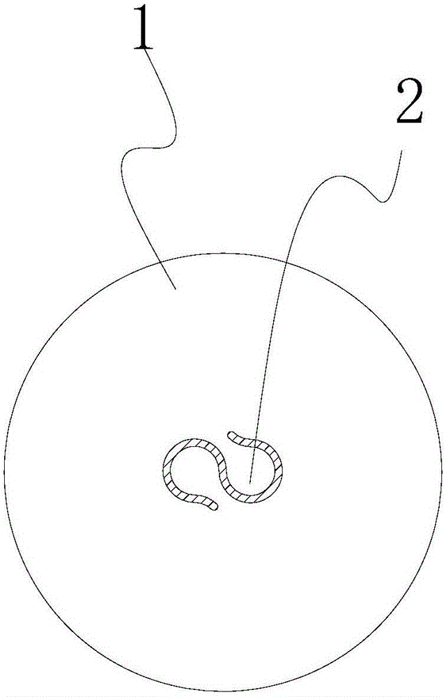
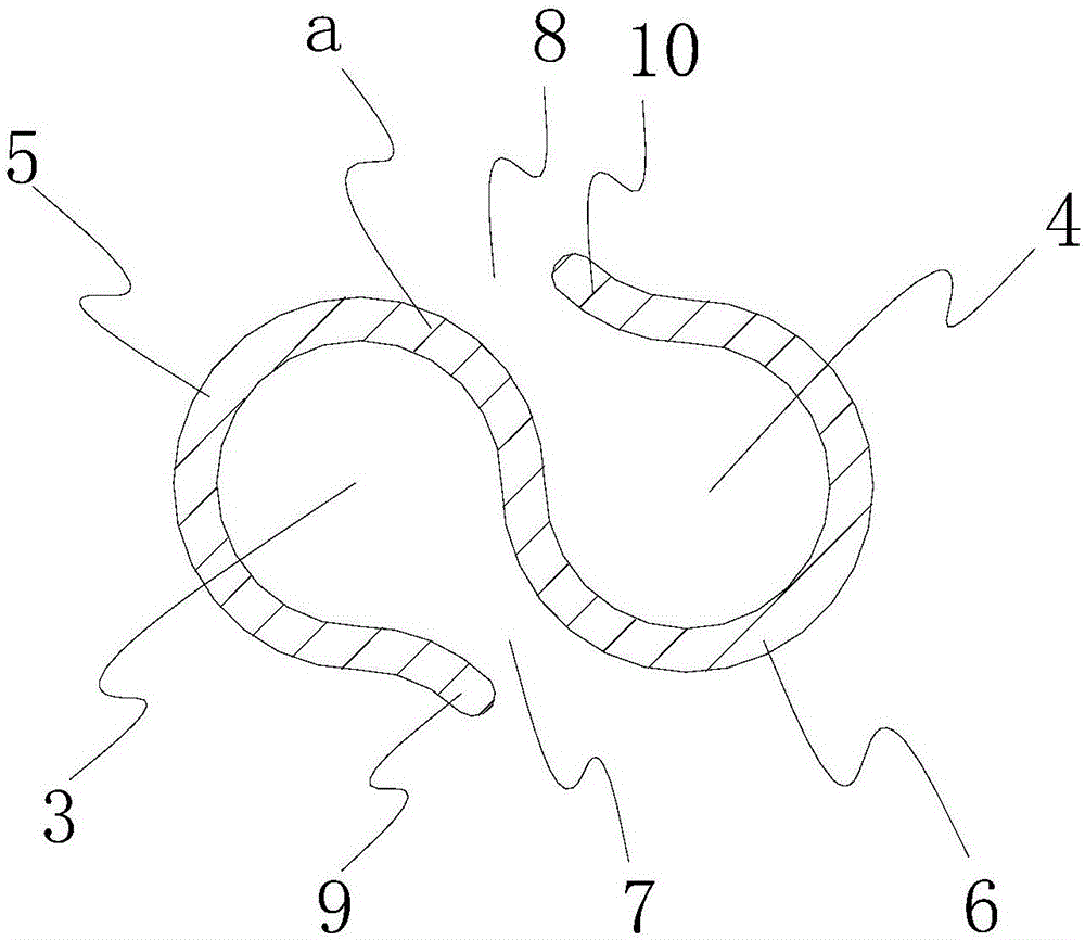
[0038] The arc-shaped slit of the present invention can be provided with two, three or more. In a specific embodiment of the present invention, the arc-shaped slit is provided with two sections, which are respectively denoted as the first slit 5 and the second slit. Gap 6. refer to figure 2 , the first slit 5 and the second slit 6 are respectively in the shape of a non-closed circular arc, the size and shape of the two slits are consistent, and the two are connected together to form an S shape as a whole, and relative to their connected positions Centrosymmetric. The first slit 5 and the second slit 6 of the present invention can be formed simultaneously, for example, the first slit 5 and the second slit 6 of the present invention can be formed by etching the diaphragm body 1 .
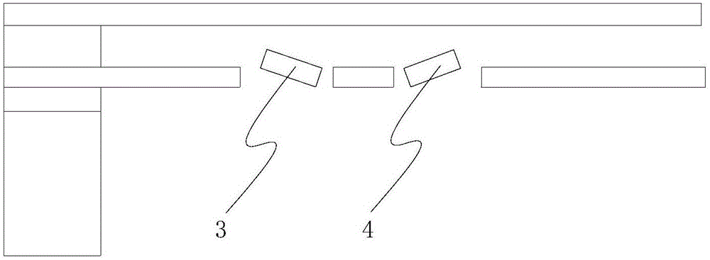
[0039] Since the first slit 5 and the second slit 6 are set on the diaphragm body 1, the first slit 5 and the second slit 6 jointly form the first valve flap 3 and the second valve flap on the diap...
Embodiment 2
[0043] In this embodiment, in order to increase the pressure relief capacity of the pressure relief device 2, the arc-shaped slit is provided with three sections, which are respectively recorded as the first slit 5, the second slit 6, and the third slit 5a that are sequentially connected together. ,refer to Figure 4 . Based on a similar principle to Embodiment 1, the first slit 5, the second slit 6, and the third slit 5a jointly form a first valve flap, a second valve flap, and a third valve flap on the diaphragm body 1, and The first valve flap is connected to the first neck of the diaphragm body, the second valve flap is connected to the second neck of the diaphragm body, and the third valve flap is connected to the third neck of the diaphragm body.
[0044] The first slit 5, the second slit 6, and the third slit 5a are respectively in the shape of a non-closed arc, and the size and shape of the three slits are consistent, so that after the three slits are connected togeth...
Embodiment 3
[0049] In this embodiment, the arc-shaped slit is provided with four sections, which are respectively recorded as the first slit 5, the second slit 6, the third slit 5a, and the fourth slit 6a which are sequentially connected together. Refer to Figure 5 . These four gaps together form the first disc, the second disc, the third disc, and the fourth disc on the diaphragm body 1, and respectively connect the first disc, the second disc, and the third disc. 1. The fourth disc and the first neck, the second neck, the third neck, and the fourth neck of the diaphragm body 1 . The structure of this embodiment is similar to that of Embodiment 3, and will not be described in detail here.
[0050] The vibrating membrane of the present invention can be applied in MEMS microphones, thereby improving the anti-sound pressure capability of MEMS microphones, for this reason, the present invention also provides a kind of MEMS microphone, and it comprises substrate, back pole, and forms flat c...
PUM
 Abstract
Description
Claims
Application Information
 - R&D
- Intellectual Property
- Life Sciences
- Materials
- Tech Scout
- Unparalleled Data Quality
- Higher Quality Content
- 60% Fewer Hallucinations
Browse by: Latest US Patents, China's latest patents, Technical Efficacy Thesaurus, Application Domain, Technology Topic, Popular Technical Reports.
© 2025 PatSnap. All rights reserved.Legal|Privacy policy|Modern Slavery Act Transparency Statement|Sitemap|About US| Contact US: help@patsnap.com