Eureka AIR delivers breakthrough ideas for toughest innovation challenges, trusted by R&D personnel around the world.

High-nitrogen steel pressure welding device and method for welding high-nitrogen steel by using same

A technology of pressure welding and high nitrogen steel, applied in the direction of auxiliary devices, welding media, welding equipment, etc., can solve the problems of inconspicuous effect, difficulty in overcoming the loss of nitrogen element, etc., achieve reasonable composition, improve mechanical properties, weld good seam quality

Inactive Publication Date: 2017-01-25
SUZHOU UNIV
View PDF6 Cites 20 Cited by
  • Summary
  • Abstract
  • Description
  • Claims
  • Application Information

AI Technical Summary

Problems solved by technology

Although research results have shown that suitable laser welding conditions can avoid the loss of nitrogen and nitrogen pores in the weld zone of high-nitrogen steel, the microstructure and performance characteristics of the weld zone under laser welding conditions are still an important issue, and further research is needed.
For other fusion welding processes, the problem of nitrogen loss in the weld zone is still difficult to overcome. At the same time, quality defects such as welding cracks and nitride precipitation must also be considered.
At present, the conventional welding process suitable for high-nitrogen steel is carried out under normal pressure conditions. By increasing the nitrogen ratio in the welding shielding gas, it can play a role in fixing nitrogen in the molten pool to a certain extent, but the effect is not obvious, especially when the It is very difficult to increase the nitrogen content of the weld to more than 90% of the nitrogen content of the base metal

Method used


Image

  • High-nitrogen steel pressure welding device and method for welding high-nitrogen steel by using same

Examples


Embodiment 1

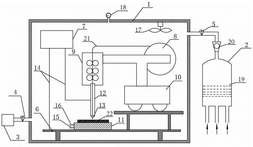
[0033] See attached figure 1 , a high-nitrogen steel pressurized welding device, comprising a closed welding chamber 1, a gas mixing chamber 2, a vacuum pump 3; Valves 4 and 5 are respectively set on the gas pipeline and the gas pipeline connecting the airtight welding room and the vacuum pump; the airtight welding room is equipped with a support 6, a welding power supply 7, a welding wire rack 8, and a wire feeding mechanism 9; a trolley 10 is set on the support; a welding wire rack It is installed on the trolley with the wire feeding mechanism; a cooling plate 11 is arranged above the bracket; a welding wire sleeve 12 is connected under the wire feeding mechanism; a welding gun 13 is connected to the end of the welding wire sleeve; the welding power supply is connected to the welding wire sleeve, The bracket is connected; the cooling plate is a water-cooled copper plate, and the circulating water circuit is set inside as a cold source, and the water body inlet and outlet are...

Embodiment 2

[0035] A device for pressurized welding of high-nitrogen steel, comprising an airtight welding chamber, a gas mixing chamber, and a vacuum pump; the airtight welding chamber communicates with the gas mixing chamber and the vacuum pump through gas pipes, and the air pipe connecting the airtight welding chamber and the gas mixing chamber and The airtight welding chamber and the vacuum pump are respectively provided with valves on the gas pipelines; the airtight welding chamber is equipped with a support, welding power supply, welding wire rack, and wire feeding mechanism; a trolley is set on the bracket; There is a cooling plate; the welding wire sleeve is connected under the wire feeding mechanism; the welding torch is connected to the end of the welding wire sleeve; the welding power supply is connected to the welding wire sleeve and the bracket through the electrode wire respectively; the cooling plate is a water-cooled copper plate, and a circulating water circuit is set insid...

Embodiment 3

[0037] A device for pressurized welding of high-nitrogen steel, comprising an airtight welding chamber, a gas mixing chamber, and a vacuum pump; the airtight welding chamber communicates with the gas mixing chamber and the vacuum pump through gas pipes, and the air pipe connecting the airtight welding chamber and the gas mixing chamber and The airtight welding chamber and the vacuum pump are respectively provided with valves on the gas pipelines; the airtight welding chamber is equipped with a support, welding power supply, welding wire rack, and wire feeding mechanism; a trolley is set on the bracket; There is a cooling plate; a welding wire sleeve is connected under the wire feeding mechanism; a welding torch is connected to the end of the welding wire sleeve; the welding power supply is respectively connected to the welding wire sleeve and the bracket through the electrode wire; the cooling plate is a hollow copper plate, and a dry ice block is installed inside to source; th...


PUM


Abstract

The invention discloses a high-nitrogen steel pressurized welding device and a method for welding high-nitrogen steel by using the device, comprising an airtight welding chamber, a gas mixing chamber, and a vacuum pump; the airtight welding chamber communicates with the gas mixing chamber and the vacuum pump respectively through gas pipelines ;The airtight welding room is equipped with bracket, welding power supply, welding wire frame, wire feeding mechanism and welding torch; the cooling plate is arranged above the bracket; the welding wire sleeve is connected under the wire feeding mechanism; the welding power supply is connected with the welding wire sleeve and the bracket through electrode wires respectively The cold source is set in the cooling plate; the welding base metal is placed on the cooling plate; the raw material gas is mixed in the gas mixing chamber and then input into the airtight welding room; the position of the welding wire and the welding torch is adjusted, the welding power is turned on, and welding is carried out. By controlling the system shielding gas composition, system total pressure and cooling parameters, the nitrogen content in the high-nitrogen steel weld can be fixed, and the mechanical properties of the high-nitrogen steel weld can be improved. Using the system of the present invention for high-nitrogen steel welding, the nitrogen content of the weld can reach More than 95% of the base material.

Description

technical field [0001] The invention belongs to the technical field of welding metallurgy, and in particular relates to a pressure welding device suitable for high nitrogen steel and a method for welding high nitrogen steel with the device. Background technique [0002] High-nitrogen steel refers to the steel whose actual nitrogen content exceeds the limit value that can be achieved by preparing materials under normal pressure (0.1Mpa). It is a new type of engineering material developed with the advancement of metallurgical technology in recent years. According to the content of nitrogen in austenitic stainless steel, nitrogen-containing austenitic stainless steel can be divided into nitrogen control type ([N]=0.05%~0.10%) and medium nitrogen type ([N]=0.10%~0.40%) And high nitrogen type ([N] > 0.40%), while the nitrogen content in ferritic and martensitic stainless steel can be called high nitrogen steel as long as it is greater than 0.08%. [N] in high-nitrogen steel ac...

Claims


Application Information

Patent Timeline
IPC IPC(8): B23K35/38B23K37/00B23K31/02
CPCB23K35/383B23K31/02B23K37/00
Inventor 屈天鹏王德永王慧华田俊苏丽娟徐周孙旭安
Owner SUZHOU UNIV
Why Eureka
Eureka Blog
Learn More