
Organic electroluminescent device

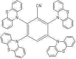
An electroluminescent device and luminescent technology, applied in the OLED field, can solve the problems of large band gap, high driving voltage, and inability to fully use energy effectively, and achieve good stability, high photoluminescence efficiency, and low price Effect

Active Publication Date: 2017-01-11
TSINGHUA UNIV
View PDF3 Cites 13 Cited by
  • Summary
  • Abstract
  • Description
  • Claims
  • Application Information

AI Technical Summary

Problems solved by technology

The article reports that the structure does not fully utilize the energy of direct recombination in the host
At the same time, common host materials are used, the band gap is large, and the required driving voltage is high

Method used


Image

  • Organic electroluminescent device
  • Organic electroluminescent device
  • Organic electroluminescent device

Examples


Embodiment 1

[0093] Synthesis of C1. Under a nitrogen atmosphere, dissolve 1 mol of potassium tert-butoxide into 20 ml of DML and stir for 1 hour, then add 1 mol of carbazole in the DML solution dropwise, and stir for 1 hour after all the addition is complete. Then, a DMF solution in which 0.2 mol of 2,3,4,5,6-pentafluorobenzonitrile was dissolved was added dropwise and stirred for 5 hours. Then the reaction solution was poured into water and filtered to obtain a solid. Separation with a chromatographic column. C1 was obtained with a yield of 90%.

[0094] Mass spectrum: 929.

[0095] Elemental analysis: C: 86.60, H: 4.35, N: 9.05.

Embodiment 2

[0097] Synthesis of C2. The reactant carbazole was replaced by tert-butyl carbazole, and C2 was obtained through the same synthesis method as in Example 1, with a yield of 91%.

[0098] Mass spectrum: 1490.

[0099] Elemental analysis: C: 86.20, H: 8.16, N: 5.64.

Embodiment 3

[0101] Synthesis of C3. The reactant carbazole was replaced by phenylcarbazole, and C3 was obtained through the same synthesis method as in Example 1, with a yield of 91%.

[0102] Mass spectrum: 1689.

[0103] Elemental analysis: C: 90.20 H: 4.83 N: 4.97.


PUM


Abstract

The present invention discloses an organic electroluminescent device, and the device comprises a light emitting layer comprising a main material and dye, wherein the doping mass concentration of the dye in the light emitting layer is 1% - 60%. At least one of the dye and the main material has the compound which has the structure shown in the formula I (shown in the description), wherein at most two of R1-R5 are H, and the others are electron-donating groups. The light emitting layer employs a brand-new thermal activation delay fluorescent material, and the single triplet energy level of the material is less than 0.3eV. The material can effectively emit delayed fluorescence, and is high in photoluminescence efficiency. Meanwhile, the material is good in stability, so a high-efficiency and long-service-life thermal activation delay fluorescent device can be obtained.

Description

technical field [0001] The invention belongs to the field of OLEDs, and in particular relates to an organic electroluminescence device in which a novel heat-activated delayed fluorescent material is used as a dye in a light-emitting layer. Background technique [0002] In the electroluminescent process of organic electroluminescent devices, mainly rely on the electronic transition of organic light-emitting materials from the excited state to the ground state to generate light. At room temperature, the luminescence produced by the electronic transition from the triplet excited state back to the ground state is extremely weak, and most of its energy is lost in the form of heat. The luminescence is mainly produced by the electronic transition from the singlet excited state to the ground state, called electric current Fluoresces. Since triplet excited states are generated three times more frequently than singlet excited states, the equivalent of 75% of the energy is not used fo...

Claims


Application Information

Patent Timeline
Patent Type & Authority Applications(China)
IPC IPC(8): H01L51/54
CPCH10K85/141
Inventor 段炼张东东朱映光张国辉刘嵩
Owner TSINGHUA UNIV
Learn More