
A selective welding carrier and its welding method

A welding method and welding board technology, which are applied in the direction of assembling printed circuits with electrical components, can solve the problems of interference of other devices, increased production management costs, and high costs of special vehicles, and can reduce the frequency of loading and unloading, and the judgment standard. Simple and clear results with high solder joint reliability

Active Publication Date: 2019-08-30
无锡市同步电子制造有限公司
View PDF9 Cites 0 Cited by
  • Summary
  • Abstract
  • Description
  • Claims
  • Application Information

AI Technical Summary

Problems solved by technology

The disadvantage of wave soldering is that there is interference from other devices and the applicable surface is low
The disadvantage of manual soldering is that it cannot meet many soldering requirements, such as substrates with a thickness of more than 2.0mm and a large-area grounding layer inside, manual soldering is almost impossible to complete
In the industry standard, level 3 electronic products require 75% through-tin, but it is difficult to measure and inspect whether to meet the 75% through-tin standard, and there are often disputes over the evaluation of this standard
And due to the influence of the ground layer of the board, it is even more difficult to achieve the requirement of 75% tin penetration
[0003] In addition, for military products, most of them meet the welding requirements of Class 3 electronic products, and there are many varieties in small batches, and the product structure is relatively complicated. Manual welding cannot meet the welding requirements, and wave soldering is not applicable. The thickness of the board is large, and most of them are plug-ins. Due to the large current during use, the requirements for noise reduction and heat dissipation of the device are high. As a result, the heat dissipation performance and overcurrent capability of the printed board must be paid attention to during the design process of the printed board. Currently, noise reduction and heat dissipation The method is to use a large area of ​​ground copper between the signal layer and the power layer, and the improvement of the heat dissipation performance of the printed board will greatly increase the difficulty of soldering manufacturability. It is difficult for welding equipment (such as electric soldering iron) in daily production. Meet the requirement of 75% through-tin
[0004] In addition, in the existing technology, the adjustment function of the selective welding carrier is weak, and the carrier is underutilized, and only one printed board can be loaded at a time. Assuming that 100 printed boards need to be welded, 100 times of loading and unloading processes are required. The preheating light tube of the machine needs to be opened 100 times and closed 100 times, and the corresponding preheating time should be multiplied by 100 times, which accelerates the aging of the preheating light tube
[0005] Moreover, the existing carriers are generally aimed at a specific type of product, and the versatility is low. Due to the wide variety of circuit boards, the size, structure, and component layout of different circuit boards are very different, and the special trays are generally not universal.
The cost of special-purpose carriers is high. On the one hand, since each special-purpose pallet is only suitable for one type of circuit board, the manufacturing cost for the pallet will be very high
On the other hand, there are a large number of special trays for maintenance and management, and the utilization rate is low, which will bring many problems to the management of the production site. Increased production management costs
There is also a universal vehicle in the prior art, but it is heavy and the utilization rate is not high

Method used

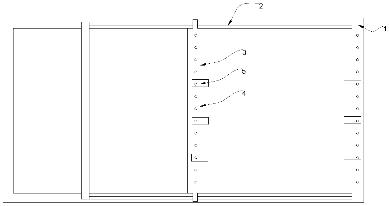
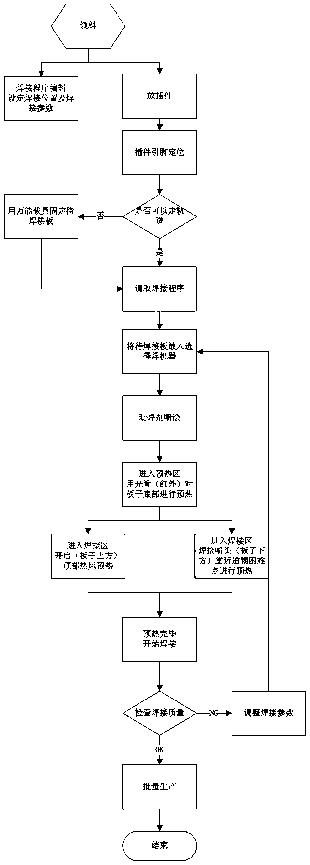

Image

  • A selective welding carrier and its welding method
  • A selective welding carrier and its welding method

Examples


Embodiment 1

[0051] Follow the steps in turn:

[0052] Step 1. Adjust the state of the selective welding machine and welding parameters, and put the welding plate into the selective welding machine; the welding parameters are:

[0053] The amount of flux sprayed is 90%;

[0054] The pre-heating stage is divided into three stages; the first stage preheating time is 20S, and the preheating power is 60% of the total power; the second stage is 20S, and the preheating power is 75% of the total power; the third stage The stage preheating time is 20S, and the preheating power is 90% of the total power.

[0055] The preheating time for the difficult point of tin penetration is 20S; the height between the welding nozzle and the board surface is 6.5mm;

[0056] The hot air preheating temperature setting temperature is 160°C (the actual board surface temperature is about 120°C);

[0057] The hot air preheating time is consistent with the welding time; the welding time is 2S; the welding temperatur...

Embodiment 2

[0065] The welding temperature in the welding parameters in Example 1 was reduced to 285° C., and other parameters and steps remained unchanged.

[0066] Experiments have proved that under this welding parameter, the requirement of 100% penetration of tin in all solder joints can be achieved. In conclusion, when other welding parameters remain unchanged, the welding temperature can be appropriately reduced.

Embodiment 3

[0068] The soldering temperature in the soldering parameters in Example 1 is reduced to 285°C, the preheating time at the point where tin penetration is difficult is reduced to 10S, and other parameters and steps remain unchanged.

[0069] Experiments have proved that under this welding parameter, the requirement of 100% penetration of tin in all solder joints can be achieved.

[0070] In conclusion, when other welding parameters remain unchanged, the preheating time of the welding head can be appropriately shortened.


PUM


Abstract

The invention discloses a selective welding carrier and a welding method thereof. The welding method comprises the following steps: adjusting a state and a welding parameter of a selective welding machine, and placing a welded plate into the selective welding machine; spraying a soldering flux; entering a preheating zone to preheat the bottom of the welded plate; entering a welding zone, and starting a hot air preheating device on the top of the welded plate to perform hot air preheating; meanwhile, preheating tin penetration difficult points; starting welding after preheating is finished; moving a welding spray head among welding spots at a uniform speed, reaching the welding spots in sequence, and performing welding; performing welding quality inspection, and returning to the step 1 to readjust the welding parameter if the welding quality is unqualified; and performing batch production if the welding quality is qualified. Through adoption of the method, 100 percent tin penetration can be reached effectively; a judgment standard is simple and clear; an industrial standard is exceeded; the welding spot reliability is enhanced; and the quality is ensured.

Description

technical field [0001] The invention relates to welding technology, in particular to a selective welding carrier and a welding method thereof. Background technique [0002] Existing selective soldering techniques include wave soldering or manual soldering. The disadvantage of wave soldering is that there is interference from other devices and the application area is low. The disadvantage of manual soldering is that it cannot meet many soldering requirements. For example, if the substrate is more than 2.0mm thick and has a large internal grounding layer, manual soldering can hardly be completed. In the industry standard, level 3 electronic products require 75% through-tin, but it is difficult to measure and inspect whether the 75% through-tin standard is met, and the evaluation of this standard is often controversial. And due to the influence of the ground layer of the board, it is even more difficult to achieve the requirement of 75% tin penetration. [0003] In addition,...

Claims


Application Information

Patent Timeline
Patent Type & Authority Patents(China)
IPC IPC(8): H05K3/34
Inventor 张海星漆长江杨坤付建
Owner 无锡市同步电子制造有限公司
Learn More