
Low-temperature denitration catalyst and preparation method thereof

A low-temperature denitrification and catalyst technology, applied in chemical instruments and methods, heterogeneous catalyst chemical elements, physical/chemical process catalysts, etc., can solve the problems of limited profit margins, catalyst manufacturing cost constraints, high prices, etc., and achieve low raw material costs , good low temperature denitrification performance, easy molding effect

Inactive Publication Date: 2017-01-04
ANHUI YUANCHEN ENVIRONMENTAL PROTECTION SCI & TECH
View PDF7 Cites 7 Cited by
  • Summary
  • Abstract
  • Description
  • Claims
  • Application Information

AI Technical Summary

Problems solved by technology

However, due to the current domestic catalytic use containing WO 3 Nanoscale TiO 2 There are fewer manufacturers, the price is higher, the catalyst manufacturing cost is greatly restricted, and the profit margin is limited

Method used


Image

  • Low-temperature denitration catalyst and preparation method thereof
  • Low-temperature denitration catalyst and preparation method thereof
  • Low-temperature denitration catalyst and preparation method thereof

Examples


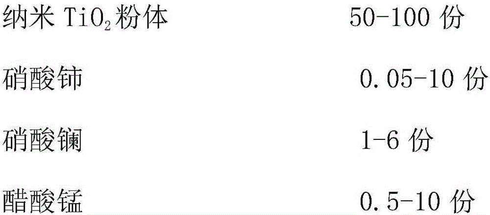
Embodiment 1

[0024] Take the components according to the following parts by weight:

[0025]

[0026] A low-temperature denitration catalyst and a preparation method thereof, the steps are as follows:

[0027] 1) Mix cerium nitrate, lanthanum nitrate, manganese acetate and antimony acetate evenly, and calcinate at 400°C for 33 hours to obtain sample a;

[0028] 2) Grinding the sample a to a particle size of 0-3 microns to obtain sample b;

[0029] 3) Match sample b with nano-TiO 2 , carboxymethyl cellulose and polyethylene oxide, mixed uniformly, and calcined at 450°C for 30 hours to obtain sample c;

[0030] 4) Grinding sample c to a particle size of 0-3 microns to obtain the product as a low-temperature denitration catalyst.

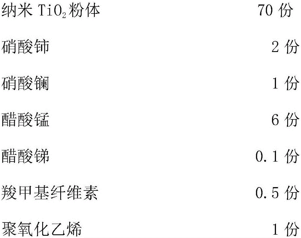
Embodiment 2

[0032]

[0033] A low-temperature denitration catalyst and a preparation method thereof, the steps are as follows:

[0034] 1) Mix cerium nitrate, lanthanum nitrate, manganese acetate, and antimony acetate evenly, and calcinate at 460°C for 35 hours to obtain sample a;

[0035] 2) Grinding the sample a to a particle size of 0-3 microns to obtain sample b;

[0036] 3) Match sample b with nano-TiO 2 , carboxymethyl cellulose and polyethylene oxide, mixed uniformly, and calcined at 400°C for 33 hours to obtain sample c;

[0037] 4) Grinding sample c to a particle size of 0-3 microns to obtain the product as a low-temperature denitration catalyst.

Embodiment 3

[0039]

[0040]

[0041] A low-temperature denitration catalyst and a preparation method thereof, the steps are as follows:

[0042] 1) Mix cerium nitrate, lanthanum nitrate, manganese acetate and antimony acetate evenly, and calcinate at 500°C for 38 hours to obtain sample a;

[0043] 2) Grinding the sample a to a particle size of 0-3 microns to obtain sample b;

[0044] 3) Match sample b with nano-TiO 2 , carboxymethyl cellulose, and polyethylene oxide, mixed uniformly, and calcined at 480°C for 35 hours to obtain sample c;

[0045] 4) Grinding sample c to a particle size of 0-3 microns to obtain the product as a low-temperature denitration catalyst.


PUM

PropertyMeasurementUnit
particle diameteraaaaaaaaaa

Abstract

The invention discloses a low-temperature denitration catalyst and a preparation method thereof. The low-temperature denitration catalyst mainly comprises 50-100 parts of nanometer TiO2 powder, 0.05-10 parts of cerous nitrate, 1-6 parts of lanthanum nitrate, 0.5-10 parts of manganese acetate, 0.05-10 parts of antimony acetate, 1-5 parts of carboxymethyl cellulose and 1-5 parts of polyoxyethylene. The method for preparing the low-temperature denitration catalyst comprises the steps of first evenly mixing and calcining cerous nitrate, lanthanum nitrate, manganese acetate and antimony acetate, adding nanometer TiO2 powder, carboxymethyl cellulose and polyoxyethylene, performing uniform mixing, and performing drying and calcination to obtain the finished product. The low-temperature denitration catalyst is low in cost, high in specific area, wide in working temperature and good in low-temperature denitration performance.

Description

technical field [0001] The invention relates to the field of catalyst manufacture, in particular to a low-temperature denitration catalyst and a preparation method thereof. Background technique [0002] my country's energy structure is dominated by coal, and coal-fired power plants produce a large amount of dust, SO x , NO x and harmful metal elements. Nitrogen oxides (NO x ) is more harmful to the environment than sulfide, NO in the atmosphere x It can cause acid rain, photochemical smog, surface water eutrophication and other problems that damage the ecological environment and endanger human health. [0003] At present, my country's NOx produced by combustion x There are three types of control methods: pre-combustion control, combustion control and post-combustion control. Pre-combustion control refers to the selection of low-nitrogen fuel, but the cost is high and there are few engineering applications; combustion control, that is, to improve the combustion method a...

Claims


Application Information

Patent Timeline
Patent Type & Authority Applications(China)
IPC IPC(8): B01J23/34B01J35/10B01D53/86B01D53/56
CPCB01D53/8628B01J23/002B01J23/34B01J2523/00B01J35/61B01J2523/3706B01J2523/3712B01J2523/47B01J2523/53B01J2523/72
Inventor 王光应刘江峰徐辉
Owner ANHUI YUANCHEN ENVIRONMENTAL PROTECTION SCI & TECH
Learn More