
Natural cold source unit

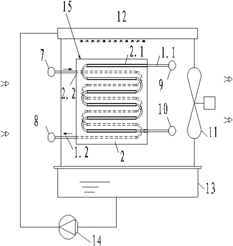
A natural cold source and unit technology, applied in refrigerators, refrigeration components, compressors, etc., can solve the problems of reduced heat exchange capacity, low operation efficiency, easy storage of dry spots, etc., to increase the evaporation surface area and improve heat exchange. Efficiency, volume reduction effect

Active Publication Date: 2016-12-07
GUANGZHOU WIDE IND
View PDF10 Cites 1 Cited by
  • Summary
  • Abstract
  • Description
  • Claims
  • Application Information

AI Technical Summary

Problems solved by technology

However, the outer surface of the heat exchange tubes of this type of coil heat exchanger is generally a smooth surface, and the heat exchange efficiency is low. At the same time, the cooling water evaporation heat exchange surface area is small, and the distance between the coils needs to be enlarged to increase the exchange between cooling water and air. heat time, thus making the entire heat exchanger bulky
Moreover, since there is no medium between the upper and lower tubes of the coil to guide the cooling water flow, when the cooling water falls from top to bottom, under the traction of the vertical wind direction, the cooling water flutters disorderly and easily produces flying water, and the water distribution on the coil is not good. Uniform, prone to dry spots, reduced heat transfer capacity and risk of scaling
[0003] The applicant’s prior Chinese patent CN 204787929U discloses a plate-tube composite evaporative condenser, the heat exchange components of which are mainly heat exchange fins; the heat exchange fins include fins and are arranged on one side of the fins The heat exchange tube, through the thermally conductive adhesive layer, makes the sheet body fully contact with the heat exchange tube, so that the heat exchange tube can produce a rib effect through the sheet body, increasing the effective heat exchange area, and at the same time, the sheet body can drain cooling water to form a continuous The water flow surface solves the problem of disorderly splashing of cooling water. However, since the heat exchange coil of the heat exchange fin is only arranged on one side of the sheet body, one side of the sheet body is caused by the heat exchange coil and the cooling water. The water temperature is high due to direct contact heat exchange, and the water temperature on the other side is low due to the indirect heat exchange between the cooling water and the heat exchange coil. low efficiency
At the same time, for heat exchange coils with large diameters, the large bending radius results in excessively large tube spacing and excessively large sheet area.
[0004] In addition, this type of heat exchange fin has only one heat exchange coil, which can only circulate one kind of fluid working medium, so that the existing natural cooling source unit using the condenser runs compressor refrigeration in summer, but can only operate in winter Heat pipe circulation or by recovering the cooling water cooling capacity of the evaporative condenser to realize natural cooling source operation, the operation efficiency is low and the cost is high

Method used


Image

  • Natural cold source unit
  • Natural cold source unit
  • Natural cold source unit

Examples


Embodiment 1

[0060] Figure 8 Shown is the first preferred embodiment of the natural cooling source unit of the present invention, the natural cooling source unit includes a compressor 16, an evaporative condenser 17, a throttling device 18, a water-cooled evaporator 19 and a shut-off valve 25. The exhaust port 16.1 of the compressor is connected to the inlet 17.2 of the heat exchange coil on one side of the sheet body, and the outlet 17.4 of the heat exchange coil on one side of the sheet body passes through the throttling device 18 and the The refrigerant inlet 19.1 of the water-cooled evaporator is connected, the refrigerant outlet 19.2 of the water-cooled evaporator is connected with the suction port 16.2 of the compressor, and the chilled water inlet 21 of the water-cooled evaporator passes through the The cut-off valve is connected to the inlet 17.1 of the heat exchange coil on the other side of the sheet, and the outlet 17.3 of the heat exchange coil on the other side of the sheet ...

Embodiment 2

[0065] Figure 9 Shown is the second preferred embodiment of the natural cooling source unit of the present invention, the natural cooling source unit includes a compressor 16, an evaporative condenser 17, a throttling device 18, a water-cooled evaporator 19 and three Shut-off valve. The exhaust port 16.1 of the compressor is connected to the inlet 17.2 of the heat exchange coil on one side of the sheet, and the throttling device and the stop valve 22 are connected to the heat exchange coil on one side of the sheet. Between the outlet 17.4 of the coil and the refrigerant inlet 19.1 of the water-cooled evaporator; the shut-off valve 23 is connected between the exhaust port of the compressor and the refrigerant outlet 19.2 of the water-cooled evaporator; the water-cooled The chilled water inlet 21 of the evaporator is connected to the inlet 17.1 of the heat exchange coil on the other side of the sheet through the shut-off valve 24, and the outlet 17.3 of the heat exchange coil ...


PUM


Abstract

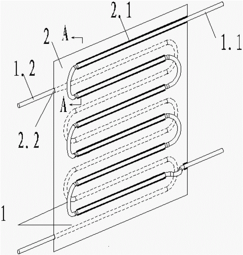
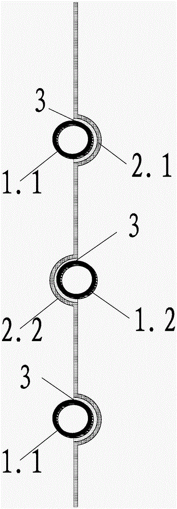
The invention discloses a natural cold source unit. The natural cold source unit comprises a compressor, an evaporation type condenser, a throttling device, a water-cooled type evaporator and a stopping device. The evaporation type condenser comprises a draught fan, a solution pump, a sprayer, a liquid trap and at least one heat exchange plate. Each heat exchange plate comprises a plate body. The two faces of the plate body are each provided with a heat exchange coiled pipe. According to the natural cold source unit, because the two faces of the plate body of each heat exchange plate of the evaporation type condenser are each provided with one heat exchange coiled pipe, the heat exchange efficiency is improved, and the effect that multiple working media conduct circulation at the same time can be achieved; and besides, the size of the natural cold source unit can be reduced under the condition that the same heat exchange efficiency is obtained, and the use demands of a user are met.

Description

technical field [0001] The invention relates to the field of heat exchange equipment, in particular to a natural cooling source unit with an evaporative condenser. Background technique [0002] In the natural cooling unit with evaporative condenser on the market at this stage, the evaporative condenser usually uses a coil heat exchange tube to form a heat exchanger, and the outer surface of the heat exchanger is cooled by spraying water, and the circulation is used to cool the heat exchanger. The spray water evaporates and takes away the heat. However, the outer surface of the heat exchange tubes of this type of coil heat exchanger is generally a smooth surface, and the heat exchange efficiency is low. At the same time, the cooling water evaporation heat exchange surface area is small, and the distance between the coils needs to be enlarged to increase the exchange between cooling water and air. Heat time, thus making the entire heat exchanger bulky. Moreover, since there ...

Claims


Application Information

Patent Timeline
Patent Type & Authority Applications(China)
IPC IPC(8): F25B1/00F25B39/04F28F1/22F28F9/26
CPCF25B1/00F25B39/04F25B2339/041F28F1/22F28F9/268
Inventor 李志明张勇谭栋陈二雄简键铃
Owner GUANGZHOU WIDE IND
Learn More