
Waste heat recovery product well system for ISC and operation method thereof

A technology for underground gasification and waste heat recovery, applied in coal gasification, underground mining, earth-moving drilling, etc., can solve the problems of no easy recovery and reusable product well equipment, blockage of product wells, and reduction of energy consumption, etc. Effective recycling and comprehensive utilization, easy recycling, and the effect of reducing energy consumption

Active Publication Date: 2016-11-16
ZHONGWEI SHANGHAI ENERGY TECH CO LTD
View PDF7 Cites 12 Cited by
  • Summary
  • Abstract
  • Description
  • Claims
  • Application Information

AI Technical Summary

Problems solved by technology

When the temperature exceeds the yield stress failure temperature of the casing material of the production well, it will eventually cause damage to the production well
[0007] (2) Damage to casing and / or cement bonded locations due to restricted thermal expansion (thermal elongation) of cemented casing
[0008] (3) Bending deformation of the product pipe due to thermal elongation of the free suspension (self-weight) product pipe in the vertical or directional product well without consideration
[0009] (4) Deterioration and damage of product well integrity due to wet corrosive syngas
[0010] (5) During the ignition process, due to the low temperature of the product well, the volatile matter of coal and the heavy components of pyrolysis products (tar, asphalt, etc.) are easy to condense in the product well and mix with solid particles and coal ash, eventually resulting in some or completely blocked
Similarly, when the load of underground gasification is reduced, the product well is blocked due to the temperature drop of the product well and the incomplete entrainment of solid and liquid impurities in the gas flow.
[0011] (6) Insufficient underground monitoring and instrumentation system for product wells, which makes it impossible to detect and deal with blockage and / or damage of product wells in advance
[0012] (7) Product wells do not have sufficient safety system equipment and treatment methods to deal with high-temperature product well damage, leakage of gas pollutants, and excessive formation pressure caused by insufficient design and configuration of abnormal system operation
[0013] (8) There is no product well equipment that is easily recycled and reusable
[0014] (9) There is no suitable process to recover the waste heat in the underground crude syngas to reduce the energy consumption of the entire underground coal gasification (ISC) process

Method used


Image

  • Waste heat recovery product well system for ISC and operation method thereof
  • Waste heat recovery product well system for ISC and operation method thereof

Examples


Embodiment 1

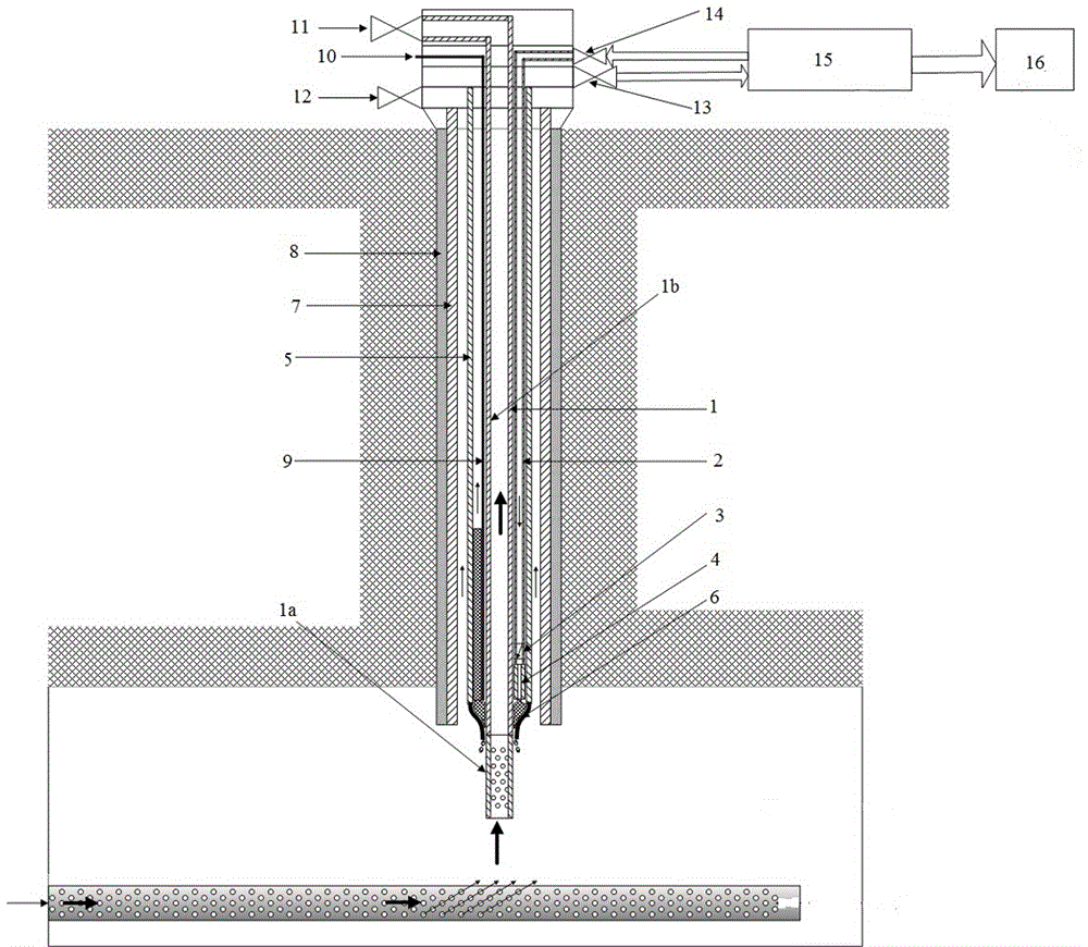
[0053] Such as figure 1 As shown, a waste heat recovery product well system for an underground coal gasification process is based on a vertical waste heat recovery product well of an underground coal gasification unit (ISC). The waste heat recovery product well system includes the following components:

[0054] A wellhead hanger, fixed on the wellhead of the product well, used to hang the relevant components of the waste heat recovery product well system;

[0055] A product pipe 1 is located in the product well and hangs freely on the wellhead hanger. The end part of the product pipe 1 is designed with holes and is provided with a number of air holes to facilitate the crude synthesis gas to enter the product pipe through the air holes and flow to the ground outlet;

[0056] A jacketed pipe 5, freely suspended on the wellhead hanger, located outside the product pipe 1 and coaxially arranged with the product pipe 1, an annular channel is formed between the jacketed pipe 5 and th...

Embodiment 2

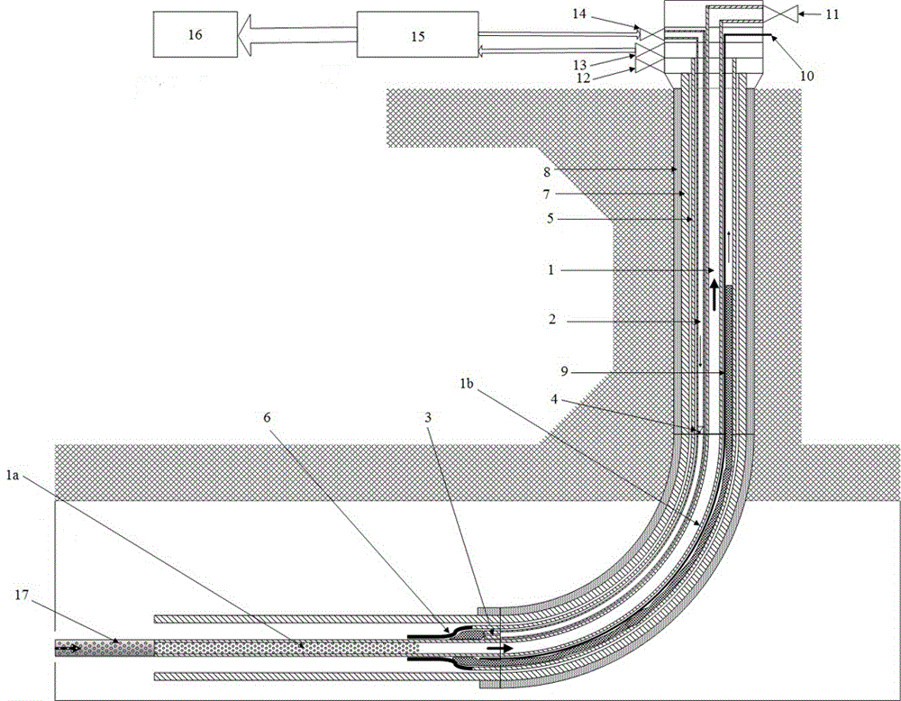
[0103] Such as figure 2 As shown, a waste heat recovery product well system for an underground coal gasification process is based on a directional waste heat recovery product well of an underground coal gasification unit, including a vertical section, an arc section, and a horizontal section. The waste heat recovery product well system The components and technical requirements including the components are basically the same as in Embodiment 1, the differences are as follows:

[0104] (a) The product pipe 1, jacket pipe 5, water-cooled pipe 2 and product well casing 7 are all in the same shape as the directional waste heat recovery product well, that is, they all include vertical sections, arc sections and horizontal sections. 1. The vertical sections of the jacketed pipe 5 and the water-cooled pipe 2 are freely suspended by the wellhead hanger, the curved section is supported by the curved section of the product well casing 7, and the horizontal part is supported by the horiz...


PUM

PropertyMeasurementUnit
Lengthaaaaaaaaaa
Apertureaaaaaaaaaa

Abstract

The invention provides a waste heat recovery product well system for ISC and an operation method of the waste heat recovery product well system for the ISC. The waste heat recovery product well system for the ISC comprises a product pipe, a jacketed pipe, a water cooling pipe, a monitoring instrument system, a product well bushing, a high-temperature high-pressure wellhead device, a ground waste heat recovery device and the like. Each component in the product well system is easy to recycle and reutilize. Heat carried out by high-temperature high-pressure downhole steam can be used for the ground production technology, turbine power generation, boiler power generation, other ground public facilities or plant life purposes and the like. By the adoption of the waste heat recovery product well system for the ISC and the operation method of the waste heat recovery product well system for the ISC, effective monitoring, control and protection of a product well can be achieved, waste heat of high-temperature crude synthesis gas is reliably and effectively recycled and comprehensively utilized, the consumption of cooling water is significantly reduced, and the requirement for downstream waste water treatment is lowered, comprehensive and efficient utilization of coal is achieved, the energy consumption of the whole ISC is lowered, and the technical problems faced by the existing ISC are finally solved.

Description

technical field [0001] The invention relates to a waste heat recovery system and an operation method, in particular to a waste heat recovery product well system and an operation method for an underground coal gasification process. Background technique [0002] Underground coal gasification (ISC) is a process that converts coal directly into gas products through controlled combustion (incomplete combustion) and gasification reactions of underground coal seams. The product gas, often called syngas, can be used as a feedstock for downstream processes such as fuel production, chemical production, power generation, and more. This process integrates well construction and completion, underground coal mining and coal gasification technology, and has the advantages of good safety, small investment, high benefit and less pollution. [0003] Drilling directly through the coal seam provides an effective channel for oxidant injection and product gas output. One well drilled for oxidant...

Claims


Application Information

Patent Timeline
IPC IPC(8): E21B43/295E21B33/04E21B17/00E21B47/06E21B47/07E21B47/00E21B33/03
CPCE21B17/00E21B33/03E21B33/04E21B43/295E21B47/00E21B47/06E21B47/07
Inventor 闵振华汪原理卡斯珀·扬·亨德利克·伯格
Owner ZHONGWEI SHANGHAI ENERGY TECH CO LTD
Learn More