
Automatic feeding tapping machine

An automatic feeding and tapping machine technology, applied in the field of machine tools, can solve problems such as difficult alignment of the center of the frosted rod, and achieve high processing efficiency, good processing consistency, and good neutrality

Active Publication Date: 2016-08-17
宁波三葵研磨材料有限公司
View PDF9 Cites 5 Cited by
  • Summary
  • Abstract
  • Description
  • Claims
  • Application Information

AI Technical Summary

Problems solved by technology

[0003] When the above-mentioned automatic feeding tapping machine is processing workpieces, because the workpieces are rigid, it is easy to align and clamp, but when processing some variable workpieces, such as frosted rods, the surface of the sandpaper is flexible. , the inner wooden core is rigid, and the center is not easy to align when clamping the frosting rod, so it is necessary to improve it

Method used


Image

  • Automatic feeding tapping machine
  • Automatic feeding tapping machine
  • Automatic feeding tapping machine

Examples


Embodiment Construction

[0027] The following descriptions are only preferred embodiments of the present invention, and therefore do not limit the protection scope of the present invention.

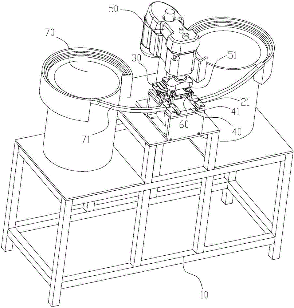
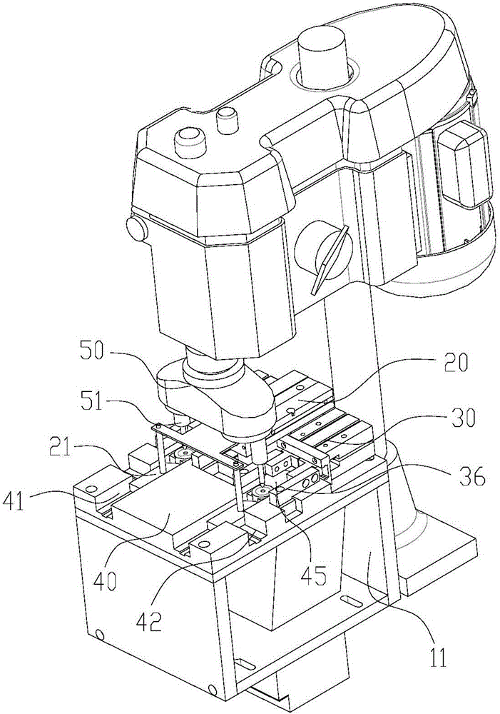
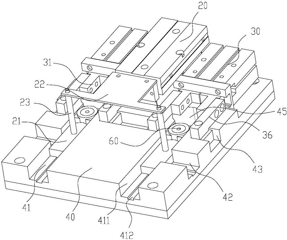
[0028] Examples, see Figure 1 to Figure 3 Shown: an automatic feeding tapping machine, including a frame 10, a machine head 50 installed on the frame 10 and a vibration plate 70 installed on the frame 10, and a tapping drill bit 51 is installed on the machine head 50 , a positioning fixture is installed on the frame 10, and the positioning fixture is installed below the tapping drill bit 51. After the workpiece 60 is clamped on the positioning fixture, the machine head 50 drives the tapping drill bit 51 to go down and tap on the workpiece 60, and the positioning The fixture includes a bottom template 40, a pusher cylinder 20 and a clamping cylinder 30. On the bottom template 40, a guide groove 41 and an inlet groove 42 connected to the guide groove 41 are provided. The guide groove 41 extends towards the directi...


PUM


Abstract

The invention discloses an automatic feeding tapping machine which has the characteristics of being accurate in alignment and high in machining efficiency. The automatic feeding tapping machine comprises a machine frame, a headpiece and vibrating disks. A tapping drill is mounted on the headpiece. A positioning fixture is mounted on the machine frame. The positioning fixture comprises a bottom template, a push cylinder and a clamping cylinder. The bottom template is provided with guiding grooves and inlet grooves. Push plates are mounted on the push cylinder and are slidably arranged in the corresponding guiding grooves. Each vibrating disk is provided with a guide groove which communicates with the corresponding inlet groove. The clamping cylinder is provided with clamping seats. The clamping seats slide towards and draw close to the centers of the guiding grooves from the two sides. Workpieces are placed in the vibrating disks and slide along the guide grooves to be arranged to the inlet grooves. The push cylinder drives the push plates to slide along the guiding grooves and push the workpieces in the guiding grooves to slide. The sidewalls of the push plates close the inlet grooves until the workpieces are clamped by the clamping seats. The tapping drill moves along the axis and conducts tapping on the workpieces. After completion of tapping, the push plates push the workpieces to fall into a discharge port.

Description

technical field [0001] The invention relates to the technical field of machine tools, in particular to an automatic feeding tapping machine. Background technique [0002] Chinese patent CN101966612A discloses a multi-head automatic feeding tapping machine, including a feeding part, a tapping part and a control part; Including the vibrating host, the vibrating inner plate, and the product splitter plate; the tapping mechanism and motor of the tapping part are installed on the main frame, the clamping mechanism is below the tapping mechanism, the motor is connected to the tapping mechanism, and the feeding pipe is connected to the clamping mechanism. A cooling oil sump is installed below the clamping mechanism. [0003] When the above-mentioned automatic feeding tapping machine is processing workpieces, because the workpieces are rigid, it is easy to align and clamp, but when processing some variable workpieces, such as abrasive rods, etc., because the sandpaper on the surfac...

Claims


Application Information

Patent Timeline
IPC IPC(8): B23G1/44B23G11/00B23Q3/08
CPCB23G1/44B23G11/00B23Q3/08B23Q2703/04
Inventor 郭飚
Owner 宁波三葵研磨材料有限公司
Learn More