
Linear motion based antenna gain direction diagram measurement method

A technology of linear motion and antenna gain, applied in the direction of antenna radiation pattern, etc., can solve problems such as errors, unusable measurement methods, inaccurate measurement results, etc., and achieve the effect of avoiding errors

Active Publication Date: 2015-06-24
成都天衡智造科技有限公司
View PDF9 Cites 18 Cited by
  • Summary
  • Abstract
  • Description
  • Claims
  • Application Information

AI Technical Summary

Problems solved by technology

However, in some practical applications, there are often some special circumstances that cause the antenna under test to be unable to rotate at will, making the traditional measurement method unusable
[0004] In order to solve the problem that the antenna under test cannot rotate at will, the existing technology proposes a measurement method that controls the reference antenna to make a circular motion around the antenna under test with the antenna under test as the center, and can also measure the gain pattern of the antenna under test
However, the current control technology is not enough to accurately control the reference antenna to make a standard circular motion, so large errors will be introduced and the measurement results will be inaccurate

Method used


Image

  • Linear motion based antenna gain direction diagram measurement method
  • Linear motion based antenna gain direction diagram measurement method
  • Linear motion based antenna gain direction diagram measurement method

Examples


Embodiment Construction

[0018] The following will clearly and completely describe the technical solutions in the embodiments of the present invention with reference to the accompanying drawings in the embodiments of the present invention. Obviously, the described embodiments are only some, not all, embodiments of the present invention. Based on the embodiments of the present invention, all other embodiments obtained by persons of ordinary skill in the art without making creative efforts belong to the protection scope of the present invention.

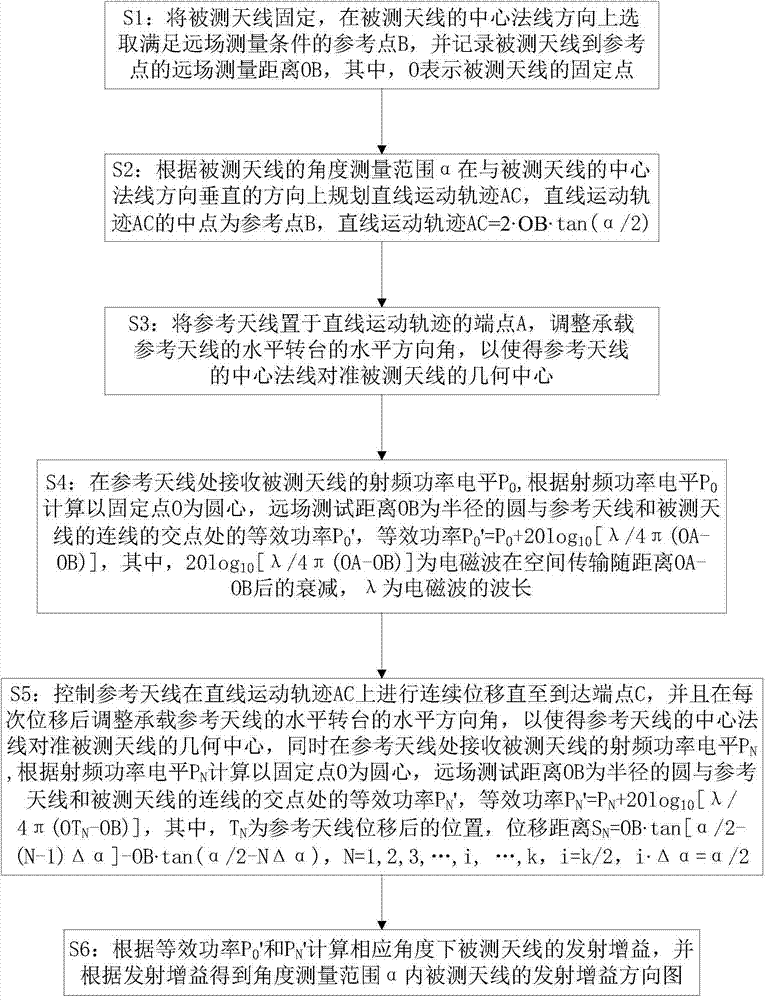
[0019] see figure 1 , is a schematic flowchart of a method for measuring an antenna gain pattern based on linear motion according to an embodiment of the present invention. The antenna gain pattern measurement method of the present embodiment includes the following steps:

[0020] S1: Fix the antenna under test, select a reference point B that satisfies the far-field measurement conditions in the normal direction of the center of the antenna under test, and r...


PUM


Abstract

The invention provides a linear motion based antenna gain direction diagram measurement method. The measurement method includes: S1, determining far-field test conditions of a to-be-tested antenna; S2, allowing the to-be-tested antenna to be vertical to the central normal direction to plan a linear motion track; S3, placing a reference antenna at the endpoint of the linear motion track and allowing the central normal of the reference antenna to align to the to-be-tested antenna; S4, according to radio frequency power level received by the reference antenna, calculating equivalent power at the intersection point of a circle taking the to-be-tested antenna as the center and the far-field test distance as the radius and a connecting line of the reference antenna and the to-be-tested antenna; S5, controlling the reference antenna to displace continuously on the linear motion track, and calculating the equivalent power after each displacement, wherein the central normal aligns to the to-be-tested antenna after each displacement; S6, calculating transmitting power according to the equivalent power of the S4 and the S5 to obtain a transmitting gain direction diagram. The gain direction diagram can be measured through the linear motion of the reference antenna.

Description

technical field [0001] The invention relates to the technical field of antennas, in particular to a method for measuring antenna gain patterns based on linear motion. Background technique [0002] As a converter of space radiated electromagnetic wave energy and transmission line guided wave, antennas are widely used in systems such as wireless communication, broadcasting, television, radar, navigation, remote sensing, radio astronomy and electronic countermeasures. The electrical parameter performance of the antenna, such as standing wave ratio, gain pattern, phase pattern, etc., is directly related to the overall performance of the system. Accurately and quickly measuring the gain pattern of the antenna is of great reference and help to the research and development, debugging and production of the antenna. [0003] The traditional antenna gain pattern measurement method is to place the antenna under test on a turntable that can adjust the pitch angle and rotate horizontall...

Claims


Application Information

Patent Timeline
IPC IPC(8): G01R29/10
Inventor 苏渊红
Owner 成都天衡智造科技有限公司
Learn More