
Robot hand and eye calibrating method based on scanner

A calibration method and robot hand technology, applied in the direction of manipulators, manufacturing tools, etc., can solve the problems of machining error, debugging error, repeated positioning accuracy and absolute positioning accuracy, etc.

Inactive Publication Date: 2015-11-04
无锡中车时代智能装备研究院有限公司
View PDF5 Cites 50 Cited by
  • Summary
  • Abstract
  • Description
  • Claims
  • Application Information

AI Technical Summary

Problems solved by technology

[0002] With the development of modern industry and robot technology, robots are more and more widely used in industry. However, due to the lack of rigidity of the robot itself, the low repeat positioning accuracy and absolute positioning accuracy, the accuracy of high-precision parts processed by robots is not good. High, unable to meet the quality requirements of the workpiece
The low precision of the robot itself is a common problem in the current robots, and there is no good solution. Therefore, it is not feasible to improve the quality of processing by improving the precision of the robot itself. Various errors to improve the quality of processing
These external errors mainly include processing errors, assembly errors, debugging errors, etc., which will also cause the positioning accuracy of the robot to be lower than the repetitive positioning accuracy, generally in the range of 2cm to 3cm

Method used

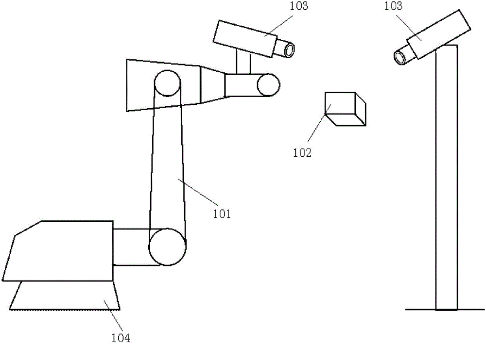
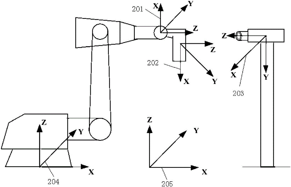

Image

  • Robot hand and eye calibrating method based on scanner
  • Robot hand and eye calibrating method based on scanner
  • Robot hand and eye calibrating method based on scanner

Examples


Embodiment Construction

[0034] The present invention will be further described below in conjunction with drawings and embodiments. It should be understood that the specific embodiments described here are only used to explain the present invention, but not to limit the present invention. In addition, it should be noted that, for the convenience of description, only parts related to the present invention are shown in the drawings but not all content.

[0035] Please refer to figure 1 as shown, figure 1 It is a schematic diagram of the scanner-based robot hand-eye calibration system provided by the present invention, in which 101 is a robot, 102 is a workpiece, 103 is a scanner, and 104 is a base of the robot. There are two types of hand-eye systems depending on where the scanner is installed. One is Eye-in-hand. In this type of hand-eye system, the scanner is fixed at the end of the robot, and the scanner moves with the end of the robot. The vision guidance system is a typical representative of thi...


PUM


Abstract

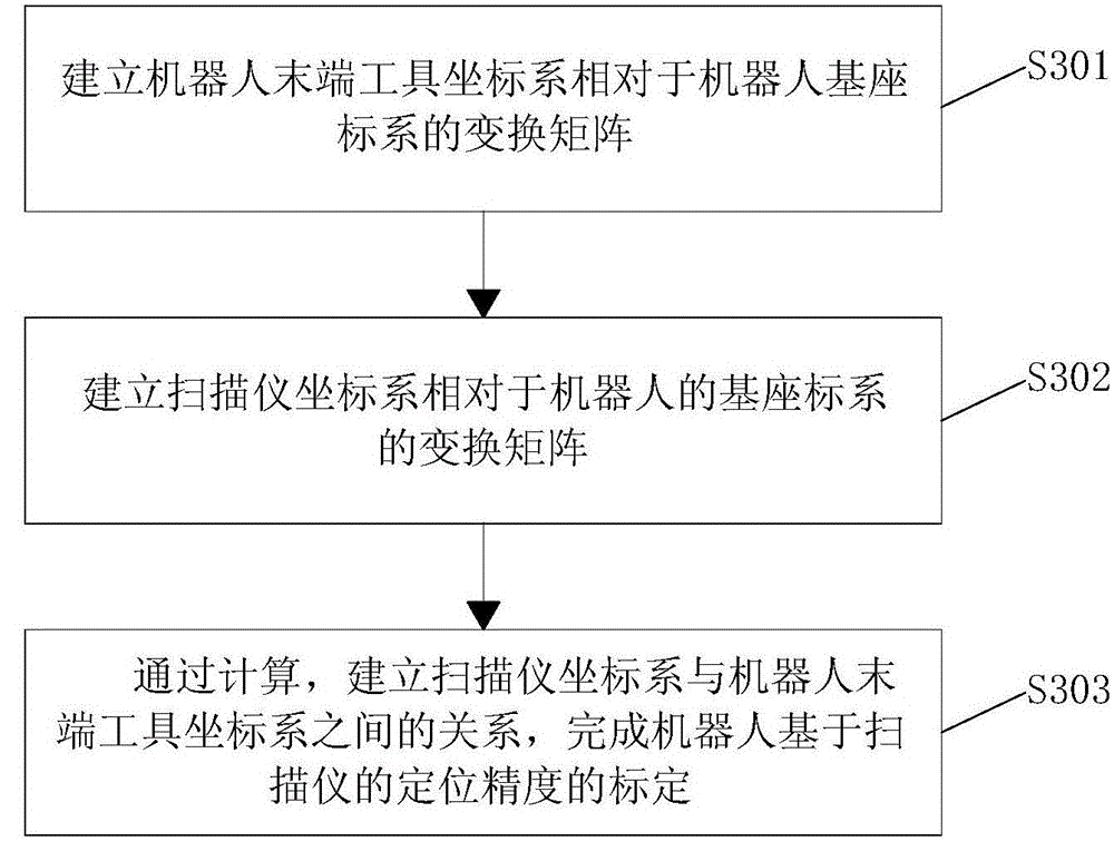
The invention discloses a robot hand and eye calibrating method based on a scanner. The robot hand and eye calibrating method comprises the steps that a transformation matrix of an end tool coordinate system of a robot relative to a base coordinate system of the robot is established; a transformation matrix of a coordinate system of the scanner relative to the base coordinate system of the robot is established; and calibration of the positioning precision of the robot based on the scanner is completed by calculating the relation between the coordinate system of the scanner and the end tool coordinate system of the robot. By means of the robot hand and eye calibrating method based on the scanner, the calibration of the positioning precision of the robot based on the scanner is completed to calculate the fixed position relation of the scanner relative to the robot so that the scanner can then be used for scanning an end clamping tool of the robot to obtain the actual position of the end tool of the robot relative to the end coordinate system of the robot; errors generated due to inaccuracy of technical operation such as installation are eliminated so that the calibrated robot can precisely scan workpieces on different occasions, and the machining precision is improved.

Description

technical field [0001] The invention relates to the technical field of industrial robots, in particular to a scanner-based robot hand-eye calibration method. Background technique [0002] With the development of modern industry and robot technology, robots are more and more widely used in industry. However, due to the lack of rigidity of the robot itself, the low repeat positioning accuracy and absolute positioning accuracy, the accuracy of high-precision parts processed by robots is not good. High, unable to meet the quality requirements of the workpiece. The low precision of the robot itself is a common problem in the current robots, and there is no good solution. Therefore, it is not feasible to improve the quality of processing by improving the precision of the robot itself. Various errors to improve the quality of processing. These external errors mainly include processing errors, assembly errors, debugging errors, etc., which will also cause the positioning accuracy ...

Claims


Application Information

Patent Timeline
IPC IPC(8): B25J13/08
Inventor 严思杰李斌徐小虎朱大虎丁汉
Owner 无锡中车时代智能装备研究院有限公司
Learn More