Method and equipment for depositing ultrahard and ultrathick DLC film layers on aircraft blade based on ion beam technology

A DLC film and aircraft blade technology, which is applied in the field of surface modification of ray beam materials, can solve the problem of easy erosion of friction coefficient aero-engines, etc., and achieve the effect of enhancing peel strength

Active Publication Date: 2016-07-20
BEIJING NORMAL UNIVERSITY
View PDF6 Cites 10 Cited by
  • Summary
  • Abstract
  • Description
  • Claims
  • Application Information

AI Technical Summary

Problems solved by technology

[0008] In view of this, one of the purposes of the embodiments of the present invention is that the ultra-low friction coefficient and super hardness of the DLC film layer solve the problem that the aircraft engine is easily eroded in the sand layer environment, and at the same time utilize the metal vacuum vapor ion source (MEVVA) and magnetic Pass

Method used


Image

  • Method and equipment for depositing ultrahard and ultrathick DLC film layers on aircraft blade based on ion beam technology
  • Method and equipment for depositing ultrahard and ultrathick DLC film layers on aircraft blade based on ion beam technology
  • Method and equipment for depositing ultrahard and ultrathick DLC film layers on aircraft blade based on ion beam technology

Examples


preparation example Construction

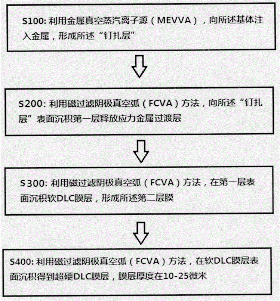
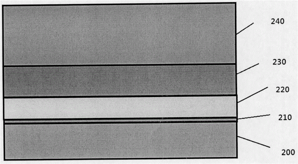
[0055] It should be noted that, in this embodiment, a DLC film is prepared on the base layer, and the selected base layer is the blade base material TC4, referring to figure 1 , which shows the DLC film preparation method of this embodiment, the preparation method includes the following steps:

[0056] S100: Using a metal vapor vacuum arc (MEVVA) ion source, injecting a first metal element into the base layer to form a metal "pinned layer".

[0057] Among them, this step is metal ion implantation to form a "pinning layer". Implantation of high-energy metal ions into the substrate can form a mixed layer of metal and substrate material to improve the bonding force between the subsequent film layer on the surface and the substrate.

Embodiment approach

[0059] The injection voltage of the first metal element is 4-15kV, the beam current intensity is 1-15mA (including the end value), and the injection dose is 1×10 15 ~1×10 17 / cm 2 (end value included), implantation depth is 70-120nm (end value included).

[0060] S200: Using a magnetic filter cathodic vacuum arc (FCVA) system, on the surface of the substrate "pinning layer", 90-degree magnetic filter deposition is used to obtain the first layer of metal internal stress release layer.

[0061] In this step, optionally, the first metal film layer may be a Ti film layer or a Ni film layer, and the thickness is 10-500 nm.

[0062] S300: Using the magnetic filter cathodic vacuum arc (FCVA) system, on the surface of the first metal internal stress release layer, 180-degree magnetic filter deposition to obtain the second layer of soft DLC film.

[0063] In this step, optionally, the cathode for arc formation to form plasma is carbon, and the thickness of the soft DLC is 10-1000 nm...


PUM

PropertyMeasurementUnit
thicknessaaaaaaaaaa
thicknessaaaaaaaaaa
thicknessaaaaaaaaaa

Abstract

The invention discloses a method and equipment for depositing ultrahard and ultrathick diamond-like carbon (DLC) film layers with excellent bonding force and high sand dust erosion resistance on the surface of an engine blade based on an ion beam technology, and the method for preparing DLC films comprises the following steps: a metal vapor vacuum arc ion source method (MEVVA) is adopted to inject a metal binding layer capable of improving the film base bonding force on the surface of the blade; a 90-degree magnetic filtered cathodic vacuum arc deposition method (FCVA) is adopted to deposit on the metal binding layer to obtain a first metal film transition layer for releasing internal stress; a 180-degree magnetic filtered cathodic vacuum arc (FCVA) deposition method is adopted to deposit on the first transition layer to obtain a second soft DLC layer; and negative-pressure 180-degree magnetic filtered deposition is changed on the second soft layer to obtain an ultrahard DLC film layer until the total film thickness is 10-25 microns. The engine blade can be preferably protected through depositing the DLC films on the engine blade, and is prevented from being damaged by erosion of sand dust.

Description

technical field [0001] The invention relates to the technical field of surface modification of ray beam materials, in particular to a method and equipment for depositing a DLC film resistant to sand and dust erosion on aircraft blades. Background technique [0002] As we all know, helicopters are characterized by good maneuverability and rarely rely on good-quality take-off and landing sites and cement runways. In most cases, the take-off and landing sites used are simple sites, or even temporary soil, sand or grass. The air contains more or less sand, dust and other particles, especially in the central and western regions of my country where the natural conditions are deteriorating, and the impact of sand and dust on aircraft and helicopters is more serious. Airplanes usually fly at higher altitudes, and there is less sand and dust in the air, which has little impact on the aircraft. However, for helicopters, its maneuverability is good, and there are often no fixed sites ...

Claims


Application Information

Patent Timeline
Patent Type & Authority Applications(China)
IPC IPC(8): C23C14/22C23C14/48C23C14/06C23C14/02
CPCC23C14/025C23C14/0605C23C14/221C23C14/48
Inventor 廖斌何卫峰罗军张旭吴先映王宇东候庆燕
Owner BEIJING NORMAL UNIVERSITY
Why Eureka
Try Eureka