
A mixed-phase mullite-type electrocatalyst for air battery or fuel cell cathode

A fuel cell cathode and air battery technology, applied in battery electrodes, circuits, electrical components, etc., can solve problems such as high overpotential, low platinum element reserves, and high price

Active Publication Date: 2021-04-23
栗豹
View PDF11 Cites 0 Cited by
  • Summary
  • Abstract
  • Description
  • Claims
  • Application Information

AI Technical Summary

Problems solved by technology

[0005] Previous studies have confirmed that platinum nanoparticles have good catalytic performance, but the reserves of platinum in the earth's crust are small and expensive, which cannot meet the requirements of large-scale production, and the activated carbon loaded with Pt will degrade with the growth of use time, resulting in catalyst loss
Although perovskite oxides are also a research hotspot, they exhibit high overpotentials in neutral solutions and will degrade in acidic solutions, so they can only be used in alkaline environments, which also limits their application. widely used

Method used


Image

  • A mixed-phase mullite-type electrocatalyst for air battery or fuel cell cathode
  • A mixed-phase mullite-type electrocatalyst for air battery or fuel cell cathode
  • A mixed-phase mullite-type electrocatalyst for air battery or fuel cell cathode

Examples


Embodiment 1

[0044] 1. A magnesium-air three-electrode battery, comprising the above-mentioned catalytic layer as positive pole, magnesium foil as negative pole, saturated Ag / AgCl solution as reference electrode, and neutral 1M NaCl aqueous solution as electrolyte. The battery container adopts H-shaped glass battery. The nickel foam coated on the catalytic layer is the current collector layer. In order to match the framework of the H battery, the nickel foam was cut into a size of 1 cm × 5 cm, and one end was coated with a catalyst substance covering an area of ​​1 cm × 2 cm, and the area was soaked in the electrolyte. During work, it is necessary to continuously blow air into the positive part of the catalytic layer to ensure the supply of oxygen.

[0045] Experiments have shown that the initial magnesium-air battery voltage can reach 1.65V, and when the current is as high as 1.0mA / cm 2 , the voltage can also reach 1.2V, and it can be maintained for 150 minutes. After that, the voltage...

Embodiment 2

[0047] 2, a kind of magnesium-air two-electrode button battery, magnesium foil, diaphragm, the catalytic layer that is coated on the foamed nickel are piled up successively, and are encapsulated in the button battery (model: CR2032), obtain magnesium-air battery unit, above-mentioned The catalytic layer is used as the positive electrode, the magnesium foil is used as the negative electrode, the neutral NaCl solution is used as the electrolyte, and the hydrophilic Celgard (Celgard) 3501 is used as the diaphragm between the two electrodes. Multiple units connected in series constitute a magnesium-air battery pack.

[0048] Connect three button battery units in series on the circuit board, and connect the positive and negative terminals to LED lights, then add 0.5 ml of 1M NaCl solution to the three batteries, wait for the electrolyte to soak into the button battery for a minute or two , 1.8V LED lights can emit light.


PUM

PropertyMeasurementUnit
current densityaaaaaaaaaa
energy conversion efficiencyaaaaaaaaaa

Abstract

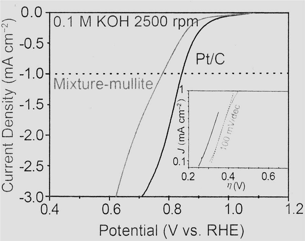
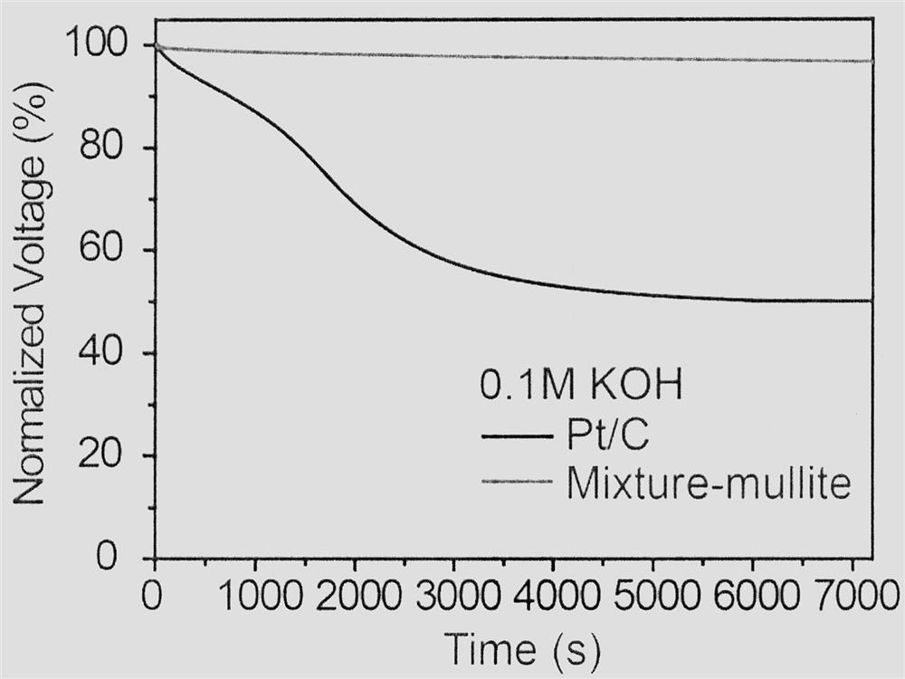
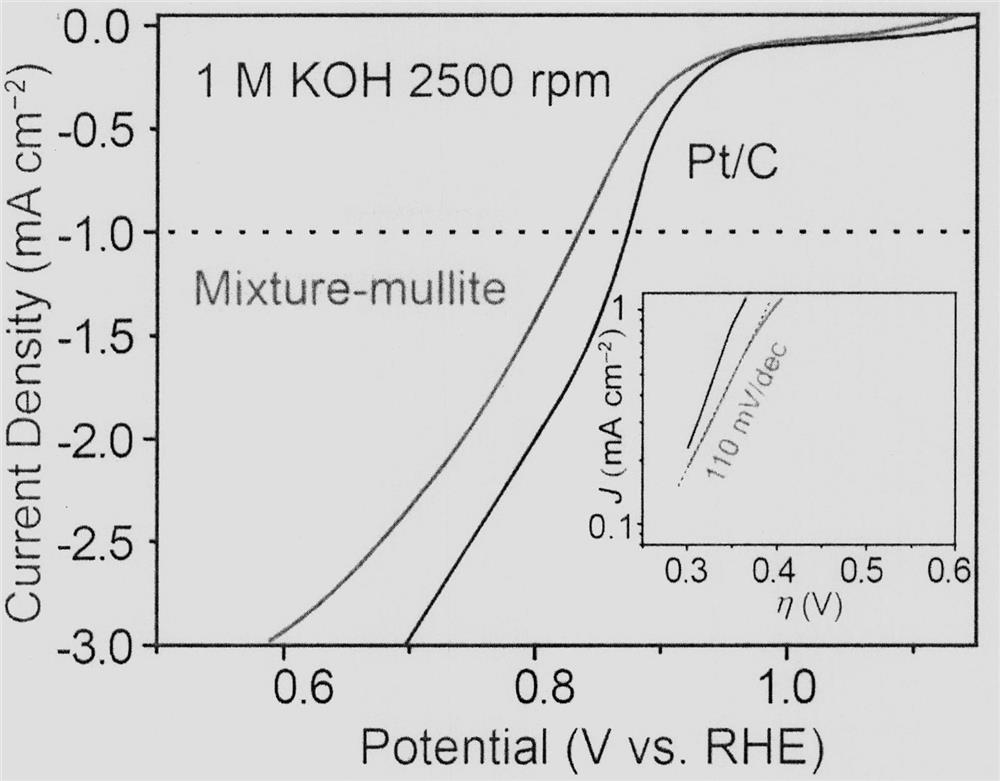
A mixed-phase mullite-type electrocatalyst for the cathode of an air battery or a fuel cell. The mixed-phase mullite material is used as a cathode catalyst for an air battery or a fuel cell. Preparation of mullite electrocatalyst, the mixed-phase oxide includes mullite phase, spinel phase and fluorite phase. It is fabricated on the cathode catalyst layer of an air battery or a fuel cell, and it is confirmed that it has a catalytic performance comparable to that of platinum. Moreover, this catalyst still has good catalytic performance and low overpotential in neutral environment. The first feature of the present invention is that it is found for the first time that the mixed-phase mullite can be used as a cathode catalyst for an air battery or a fuel cell, and the second feature is the preparation method of the catalytic layer.

Description

technical field [0001] A mixed-phase mullite electrocatalyst for an air battery or fuel cell cathode. Background technique [0002] Energy and environmental issues have always been the focus of attention. After human society entered the stage of industrialization, fossil fuels (mainly including oil, coal and natural gas) became the material basis for human survival and social progress. However, fossil fuels have also caused irreversible pollution to the natural environment, causing a large amount of waste water, waste gas, waste residue, and waste heat to be discharged. And, with the further increase of energy demand, the fossil fuels with limited reserves will decrease and will eventually be exhausted. Therefore, all countries in the world are looking for new energy sources with high energy utilization efficiency, environmental friendliness and renewable energy. [0003] Air batteries and fuel cells have become research hotspots in new energy due to their advantages of z...

Claims


Application Information

Patent Timeline
Patent Type & Authority Patents(China)
IPC IPC(8): H01M4/88H01M4/90H01M4/96
CPCH01M4/88H01M4/90H01M4/96Y02E60/50
Inventor 王卫超刘洁宇于勐刘孟寅杨志王长洪
Owner 栗豹
Learn More