
A 3D printing method of laser composite contour scanning

A 3D printing and compound contour technology, applied in the field of 3D printing, can solve the problems of difficulty in removing waste materials, low material utilization rate, and affecting processing efficiency, etc., to improve printing efficiency and material utilization rate, high printing accuracy, and high surface finish Effect

Active Publication Date: 2018-01-16
DALIAN UNIV OF TECH
View PDF5 Cites 0 Cited by
  • Summary
  • Abstract
  • Description
  • Claims
  • Application Information

AI Technical Summary

Problems solved by technology

Although the PIRP method only scans the contour for failure, it has the advantages of high efficiency and high precision compared to SLS, but it requires a heating system to pre-consolidate the entire width of the surface. The larger the width, the longer the heating time, which affects the overall processing efficiency. The utilization rate is low and it is difficult to remove waste for parts with complex inner cavity structures

Method used


Image

  • A 3D printing method of laser composite contour scanning
  • A 3D printing method of laser composite contour scanning
  • A 3D printing method of laser composite contour scanning

Examples


Embodiment Construction

[0025] specific implementation plan

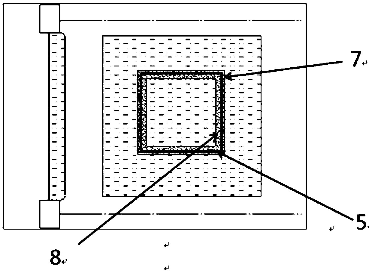
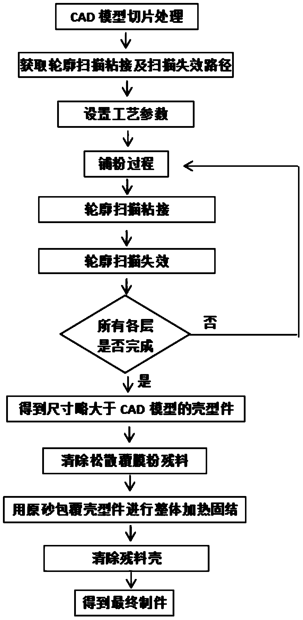
[0026] The present invention proposes a laser composite contour scanning 3D printing method, which uses a composite process of large spot laser scanning contour bonding and small spot laser scanning contour failure to carry out shell printing and manufacturing of printing materials. Specifically include the following steps:

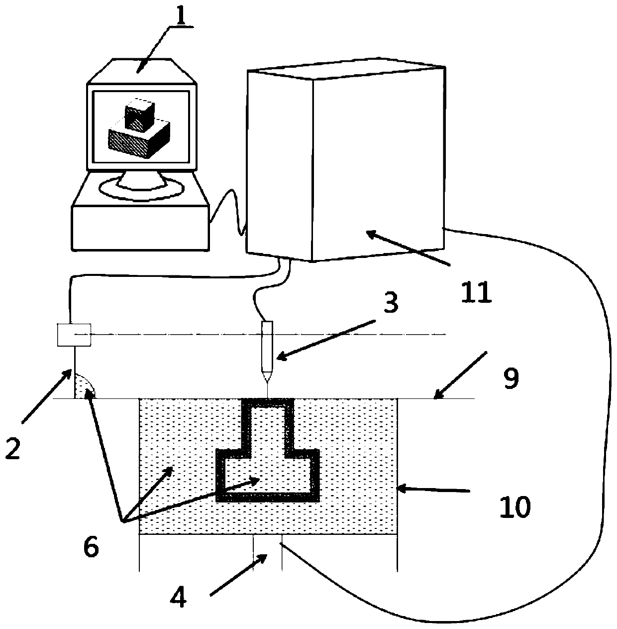
[0027] (1) Draw the three-dimensional CAD model of the part on the computer 1, use slicing software to slice the CAD model, generate model slice information, obtain the two-dimensional outline of each layer of CAD model, and obtain the two-dimensional outline data, such as figure 1 ;

[0028] (2) Process the two-dimensional contour data of the CAD model to obtain the contour scanning bonding path and contour scanning failure path;

[0029] (3) The molding cavity piston 4 descends a layer thick distance, and the powder spreading system 2 spreads the loose coated sand 6 in the forming cavity 10 to complete the powder ...


PUM

PropertyMeasurementUnit
diameteraaaaaaaaaa
thicknessaaaaaaaaaa
thicknessaaaaaaaaaa

Abstract

The invention discloses a laser hybrid profile scanning method used for 3D laser printing. In the 3D laser printing process, by utilizing adjustment and changes of spot diameters and energy densities of laser beams, light beams with different light beam diameters are obtained, namely the small-spot light beams with the high energy density are obtained. Large-spot light beams with the low energy density are used for carrying out hybrid scanning on the model profile, large spots with the low energy density are used for achieving bonding and curing of profile scanning, small spots with the high energy density are used for achieving profile scanning invalidation, and finally manufacturing of shell molds meeting the requirements for size precision and strength is completed.

Description

technical field [0001] The invention belongs to the field of 3D printing (additive manufacturing), and relates to a 3D printing device and method for laser composite contour scanning. Background technique [0002] Rapid prototyping technology is also known as 3D printing technology. Since its development in the 1980s, its superiority has been recognized by the world. At present, many universities, research institutes and enterprises at home and abroad are conducting research on 3D printing technology. 3D printing technology is a typical stacked manufacturing technology. The 3D model of the target part is sliced ​​and processed layer by layer according to a certain layer thickness to obtain 2D data, processed layer by layer, and layer by layer. [0003] At present, the laser is used as the energy source and the printing powder materials are mainly divided into the following methods: Selective Laser Sintering (SLS), Selective Laser Melting (SLM), Profile Failure (Profile) Inv...

Claims


Application Information

Patent Timeline
Patent Type & Authority Patents(China)
IPC IPC(8): B29C64/386B33Y50/00B33Y50/02
Inventor 姚平坤童强张雪姚山
Owner DALIAN UNIV OF TECH
Learn More