On-site Implementation Method of Dynamic Rod Engraving in Nuclear Power Plant

A technology of dynamic rod cutting and nuclear power plants, applied in nuclear power generation, nuclear engineering, nuclear reactor monitoring, etc., can solve the problems of exceeding acceptance standards, loss of economic benefits of commercial power plants, and failure to optimize the sequence of zero-power physical tests, etc.

Active Publication Date: 2017-12-12
CHINA GENERAL NUCLEAR POWER CORP +1
View PDF4 Cites 1 Cited by
  • Summary
  • Abstract
  • Description
  • Claims
  • Application Information

AI Technical Summary

Problems solved by technology

[0006] (1) Correction of space effects: In order to use the reactivity equation derived from the point reactor model, the core needs to be in an asymptotic equilibrium state
[0007] (2) Determination of the background compensation current: the determination method of the background compensation current provided by Westinghouse Corporation of the United States is not suitable for the background compensation current of different nuclear power plant units, resulting in a far difference between the measurement results and the traditional rod marking method, which directly leads to some Control Rod Measured Value Wrongly Exceeds Acceptance Criteria
[0008] (3) The optimization of the engraving sequence: the dynamic engraving technology provided by Westinghouse Corporation of the United States does not consider optimizing the engraving sequence, and does not consider the changing trend of the background compensation current and the impact on the value of the rods in combination with the characteristics of specific nuclear power plant units. , resulting in the measurement results of the dynamic rod marking technology being adversely affected by the background compensation current to a certain extent, which directly affects the results and accuracy of the dynamic rod marking technology
[0009] (4) Optimization of zero-power physical tests: The dynamic engraving technology provided by Westinghouse Corporation of the United States does not consider optimizing the sequence of zero-power physical tests, and does not consider the positive moderator temperature and background compensation current in combination with the characteristics of specific nuclear power plant units. The changing trend and influence on the test results and test time lead to the measurement results of the dynamic inscription rod technology being adversely affected by the background compensation current to a certain extent, which directly affects the accuracy and results of the zero-power physical test, and the unfavorable influence of commercial power plants. Necessary loss of economic benefits
However, traditional reactivity meters cannot meet these requirements

Method used


Image

  • On-site Implementation Method of Dynamic Rod Engraving in Nuclear Power Plant
  • On-site Implementation Method of Dynamic Rod Engraving in Nuclear Power Plant
  • On-site Implementation Method of Dynamic Rod Engraving in Nuclear Power Plant

Examples


Embodiment 1

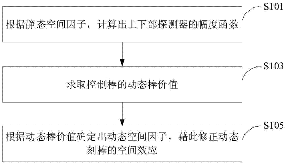
[0027]This embodiment provides a method for correcting space effects in the on-site implementation method of dynamic rod carving in a nuclear power plant, by introducing static space factors and dynamic space factors to ensure that the dynamic rod carving method can obtain correct reactivity measurement values ​​during field tests.

[0028] The static space factor is actually a normalized space distribution function. Generally, the static space factor = the simulated static detector signal when inserting rods / the simulated static detector signal when all rods are pulled out (ARO, All Rods Out).

[0029] The rod value corresponding to the reactivity obtained by the static space factor is not completely equal to the rod value obtained by the traditional method, because the spatial distribution of delayed neutrons has not yet reached the progressive equilibrium. Here, the rod value obtained by dynamic carving rod through static space factor and reactivity equation is called (calc...

Embodiment 2

[0050] This embodiment provides a method for determining the background compensation current in the on-site implementation method of dynamic rod marking in nuclear power plants, which is implemented based on the ADRC with DRWM mode developed by Westinghouse Corporation of the United States, and includes the following steps S201-S206.

[0051] Step S201: Confirm that all the control rods are set to manual (automatic is prohibited), and the maximum moving speed of all control rods has been set, for example, 72 steps / min. The control rod group is divided into three categories, namely, the power compensation rod group (G rod and N rod, including such as G1, G2, N1, N2), the temperature regulation rod group (R rod) and the shutdown rod group (S rod, including such as SA, SB, SC and SD).

[0052] Step S202: Set the ADRC to the DRWM mode, and adjust the range setting of the multi-stroke recorder.

[0053] Step S203: Manually analyze and record the boron concentration of the main cir...

Embodiment 3

[0063] In order to explore the influence of the background current setting on the rod value measurement results, sensitivity analysis was carried out by using different background current correction test fluxes. Figure 4 It schematically shows the trend of the background compensation current changing with the state of the core during the overhaul of a nuclear power plant, where "diluted to about CBcri+125ppm" means that the theoretical boron concentration is 125ppm higher, and "R1 value is too large, Rin" means R The control rod group is inserted into the 5-step withdrawal position of the reactor core, and "R+G2in" means that both the R and G2 control rod groups are inserted into the 5-step withdrawal position of the reactor core. It can be seen that when the unit is in thermal shutdown and ARI state (non-standard thermal shutdown), the PRC background is measured, and it is found that when the background compensation current has just been set, the readings of the upper and low...


PUM


Abstract

The invention relates to a nuclear power station dynamic rod worth measurement on-site enforcement method. The method comprises the following steps: correcting spatial effect during a measurement process, determining local offset current, optimizing a sequence of rod worth measurement and a sequence of zero-power physics testing, and arranging an advanced reactivity meter and then inspecting the advanced reactivity meter. In the improved dynamic rod worth measurement on-site enforcement method, each group of control rod can independently measure without interference effect, rod worth is not dependent on worth of a reference rod, the reliability of measuring result is high; steps of boronation and dilution are not employed during the measurement process, the obtained maximum reactivity is dependent on reactivity of an original state, so that the enforcement method is safer; measuring operation is simple, man-made error probability is greatly reduced; the dynamic rod worth measurement on-site enforcement method can provide the control rod worth by taking position as function, and provides a reactor core design model required by more data verification security analysis; measurement efficiency is increased, the overhaul time of key paths can be greatly shortened by at least about a dozen hours in each overhaul; and movement of the control rod and discharge of radioactive waste can be reduced.

Description

technical field [0001] The invention relates to the technical field of digital control of nuclear power plants, in particular to related methods involved in the on-site implementation of dynamic marking of nuclear power plants, including the correction of space effects during the measurement process, the determination of local compensation currents, the order of marking sticks, and the optimization of the sequence of zero-power physical tests , and the setting and inspection of advanced reactivity instruments, etc. Background technique [0002] The control rod is an indispensable control component for the emergency control and power regulation of the nuclear reactor. Under normal working conditions, by adjusting the position of the control rod, the normal start-up and shutdown of the reactor can be realized, so that the reactor can operate at a given power level or the reactor Power regulation; under accident conditions, the emergency shutdown can be realized by quickly inse...

Claims


Application Information

Patent Timeline
Patent Type & Authority Patents(China)
IPC IPC(8): G21C17/10G21C17/112
CPCY02E30/30
Inventor 李志军郭远熊谭世杰李文胡汝平冯晓明徐志献彭松赵兵全易林洪志强张享明
Owner CHINA GENERAL NUCLEAR POWER CORP
Why Eureka
Try Eureka