
A Realization Method of Waveguide-Microstrip Transition Structure in Millimeter Wave Band

A millimeter wave frequency band and transition structure technology, applied in the microwave field, can solve the problems of small size, shortened suspension strip line, and deviation of input impedance of probe circuit from design value, etc.

Active Publication Date: 2018-03-09
XIAN INSTITUE OF SPACE RADIO TECH
View PDF3 Cites 2 Cited by
  • Summary
  • Abstract
  • Description
  • Claims
  • Application Information

AI Technical Summary

Problems solved by technology

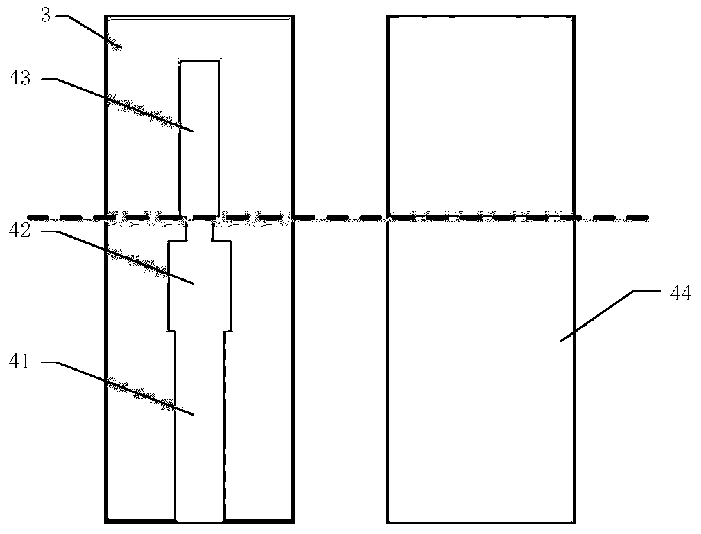
Existing research results are focused on how to optimize the probe width, length and distance from the short-circuit surface of the waveguide from the perspective of theoretical simulation, so as to make the waveguide-microstrip probe transition performance better, but it is not practical in engineering applications. Difficult to find: The quality of the transition performance not only depends on the optimized assembly of parameters such as the probe width, length, and distance from the waveguide short-circuit surface, but also is closely related to assembly, because the waveguide-micro The size of the waveguide cavity with the probe transition structure and the transmission transition microstrip line are often relatively small, and it is difficult to ensure such Figure 1~2 In the ideal assembly state shown, the errors introduced by assembly are inevitable, mainly manifested in two problems: ① Due to the liquid metal properties of the conductive adhesive, when the back of the dielectric substrate is pasted into the narrow groove with conductive adhesive, the conductive The glue will overflow toward the direction of the probe circuit, resulting in relatively short suspension strip lines and changes in input impedance; ②The starting ends of the high and low impedance matching lines cannot be completely aligned with the connection between the waveguide and the narrow slot, resulting in high impedance of the actual transition structure The line equivalent inductance value and the input impedance of the probe circuit deviate from the design value
In the millimeter wave or even higher frequency bands, the influence of parasitic parameters introduced by these deviations is more obvious, which affects the performance of the waveguide-microstrip probe transition, and the consistency of batch assembly is poor, which is also difficult to solve perfectly through manual assembly. The problem

Method used


Image

  • A Realization Method of Waveguide-Microstrip Transition Structure in Millimeter Wave Band
  • A Realization Method of Waveguide-Microstrip Transition Structure in Millimeter Wave Band
  • A Realization Method of Waveguide-Microstrip Transition Structure in Millimeter Wave Band

Examples


Embodiment

[0036] In this embodiment, a 37GHz waveguide-microstrip probe transition structure is obtained by using the implementation method of the present invention, which is used for a 37GHz receiving front-end component of a microwave imaging detector.

[0037] Among them, the system's requirements for the 37GHz receiving front-end components are as follows:

[0038] Working frequency: 37GHz±1GHz;

[0039] Noise figure: ≤4.0dB;

[0040] Waveguide model: BJ320;

[0041] Number of channels: 6 channels.

[0042] From the above index requirements, it can be seen that the 37GHz receiving front-end component has strict requirements on the insertion loss and assembly consistency of the waveguide-microstrip probe transition structure. Combined with the analysis of the entire receiving front-end link, the corresponding waveguide-microstrip probe The technical indicators of the transition structure with probes are as follows:

[0043] Insertion loss: <0.4dB;

[0044] Return loss: <-17dB. ...


PUM


Abstract

The invention provides a method for realizing a waveguide-microstrip transition structure in the millimeter wave frequency band. The steps of the method include: 1. opening a narrow groove on the wide wall on one side of the waveguide; Metal thin film pattern sputtering is carried out on both sides, 50 ohm microstrip transmission line, microstrip impedance transformation line, positioning mark circuit and probe circuit are formed on the front side, and a metal layer with an extension part is formed on the back side, and the probe circuit is formed by traditional suspension The stripline is improved to a combined form of a microstrip line and a suspended stripline; 3. The back of the dielectric substrate is bonded in the narrow slot with conductive glue, and the probe circuit is vertically suspended in the waveguide. The waveguide-probe circuit transition structure obtained by this method is suitable for microwave products in the millimeter wave or even higher frequency bands. On the premise of ensuring the excellent performance of the transition structure, it greatly reduces the uncertainty caused by manual assembly and ensures Consistency of product assembly.

Description

technical field [0001] The invention relates to the field of microwave technology, in particular to a method for realizing a waveguide-microstrip transition structure in the millimeter wave frequency band. Background technique [0002] With the continuous improvement of the application frequency band, the engineering realization of microwave products is inseparable from the waveguide-microstrip transition conversion. Low insertion loss, small reflection coefficient, and good assembly consistency are the most basic requirements for this type of structure. The commonly used waveguide- There are three main forms of microstrip transition conversion structure: (1) antipolar fin line transition; (2) stepped and ridged waveguide transition; (3) coupled probe transition, where coupled probe transition includes coaxial probe transition and probe The circuit transitions in two forms. In the millimeter wave frequency band, many systems have special requirements for volume and weight, ...

Claims


Application Information

Patent Timeline
Patent Type & Authority Patents(China)
IPC IPC(8): H01P11/00
Inventor 吴刚徐辉李兵张晓阳
Owner XIAN INSTITUE OF SPACE RADIO TECH
Learn More