Laser-induced wheel pair surface strengthening and finishing processing method

A technology of finishing and surface strengthening, applied in metal processing, heating inorganic powder coating, etc., can solve the problems of worker's health damage, large surface roughness, long production cycle, etc., saving machining time and surface roughness. The effect of low intensity and shortened production cycle

Active Publication Date: 2015-08-12
JIANGSU HUAYAO MACHINERY MFG
View PDF4 Cites 0 Cited by
  • Summary
  • Abstract
  • Description
  • Claims
  • Application Information

AI Technical Summary

Problems solved by technology

Although heat treatment can change the structure and properties of materials, it is easy to cause slight plastic deformation
Intermediate frequency quenching and tempering are difficult to improve the microhardness and wear resistance of the wheel set
Coarse grinding, semi-finishing, and fine grinding are the most common processing procedures for grinding wheel sets. Due to the high grinding speed and high instantaneous temperature in the grinding area during fine grinding, surface burns and grinding cracks are prone to occur, so it is very difficult to It is difficult to ensure that the outer circle of the wheel is ground to a very low surface roughness. If the surface roughness of the wheel set is large, the stress concentration will be strong, which will greatly reduce the fatigue strength of the wheel set
In addition, due to the large amount of grinding work, a large amount of oil mist or water mist will be generated during the grinding process, which will pollute the environment and cause damage to the health of workers
Therefore, the above process has problems such as low microhardness of the wheel set, poor wear resistance, large surface roughness, long production cycle, and serious environmental pollution.

Method used


Image

  • Laser-induced wheel pair surface strengthening and finishing processing method

Examples


Embodiment Construction

[0024] The specific implementation manners of the present invention will be described in detail below in conjunction with the accompanying drawings.

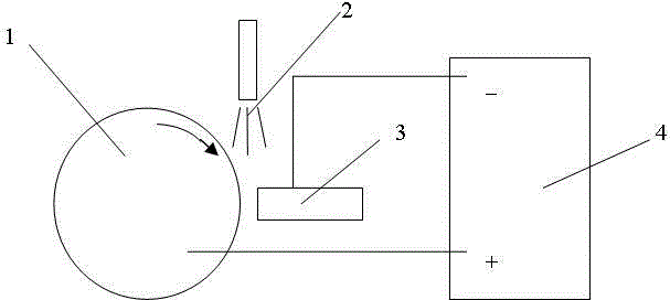
[0025] Taking the in-situ recombination of Ti(C,N) on the metal surface as an example, laser-induced strengthening was first performed on the tread and rim of the wheel. The mixing mass ratio of TiO2, formamide and carbon black powder was 5:5:4. The power is 1300W, the flow rates of acetylene and nitrogen are 6L / min and 8L / min respectively, the scanning speed of the laser beam is 400mm / min, the laser wavelength is 10.6μm, the spot diameter is 3mm, and the rotation speed of the wheel set is 7r / min. The Ti(C,N) layer with a thickness of up to 400 μm is compounded in situ on the wheel tread and the wheel rim surface, and the microhardness can reach HV2700.

[0026] Polishing was performed using the pulse current electrochemical finishing technology with the following process parameters: pulse frequency 9KHz, pulse current value 200...


PUM

PropertyMeasurementUnit
thicknessaaaaaaaaaa
microhardnessaaaaaaaaaa
thicknessaaaaaaaaaa

Abstract

The invention discloses a laser-induced wheel pair surface strengthening and finishing processing method so as to solve the problems of small microhardness, poor wear resistance, large surface roughness, long production period and severe environment pollution and the like in a conventional wheel pair manufacture process. The method comprises the following steps: 1) the wheel pair surface strengthening step: mixed powders formed by TiO2, formamide and carbon black are input with nitrogen and acetylene and the mixed powders are blown; laser beams slantly radiate the mixed powders and the nitrogen; and a wheel is rotatably arranged in the nitrogen and acetylene gas atmosphere, and Ti (C, N) is generated on a wheel pair metal surface through in-situ composite; and 2) the wheel pair finishing processing step: a neutral electrolyte is input between the wheel obtained after the laser-induced strengthening and a cathode, a clamp plate clamps the wheel to rotate, and the cathode carries out feed movement simultaneously, and finishing process is carried out on the surface of the wheel pair through the pulse electrochemical technology. The method enhances wheel pair hardness, improves surface wear resistance, reduces surface roughness and improves fatigue life.

Description

technical field [0001] The invention relates to a method for strengthening the surface of a laser-induced wheel set, and also relates to a method for combining laser-induced surface strengthening with pulse electrochemical precision finishing. Background technique [0002] Usually the wheel set is rotating and rolling, and bears the full weight of the vehicle, so it is prone to wear and tear during operation. The manufacturing process of a conventional wheel set is: wheel blank forging→rough turning outer circle→finishing outer circle and inner hole diameterintermediate frequency quenching, tempering blanking→repairing center hole→grinding outer circle→milling keyway. Although heat treatment can change the structure and properties of materials, it is easy to cause slight plastic deformation. Intermediate frequency quenching and tempering are difficult to improve the microhardness and wear resistance of the wheel set. Coarse grinding, semi-finishing, and fine grinding are ...

Claims


Application Information

Patent Timeline
Patent Type & Authority Applications(China)
IPC IPC(8): B23H5/00C23C24/08
CPCB23H5/00B23H2200/00C23C24/08
Inventor 葛兆星王辉王友余
Owner JIANGSU HUAYAO MACHINERY MFG
Why Eureka
Try Eureka