


Quick Research
Generate reliable direction feasibility study reports for your R&D in just a few steps.

Technical Q&A
Discover and master advanced knowledge NOW. Basics, ideas, possibilities, all at once.

Find Solutions
As an expert in R&D theories, this can generate solutions to your technical problems instantly.

Evaluate Feasibility
Analyze your overall solution with one click, know your potential R&D risks in advance.

Monitor Landscape
Get weekly tech updates, stay abreast of the latest tech innovations and key insights.
Transporting member for heating furnace
A technology for heating furnaces and components is applied in the fields of thermal shock resistance and corrosion resistance, and improving the thermal deformation resistance of conveying components for heating furnaces, and can solve the problems of low thermal shock resistance, damage to conveying components for heating furnaces, and thermal shock. and other problems, to achieve the effect of high thermal deformation resistance, adhesion prevention, and durability improvement
- Summary
- Abstract
- Description
- Claims
- Application Information
AI Technical Summary
Problems solved by technology
Method used
Image

Examples
Embodiment 1
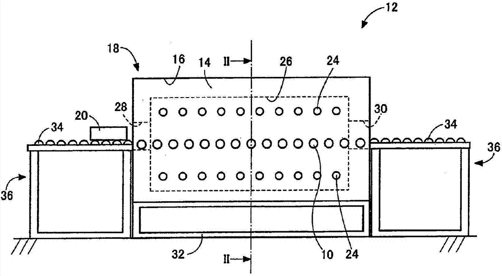
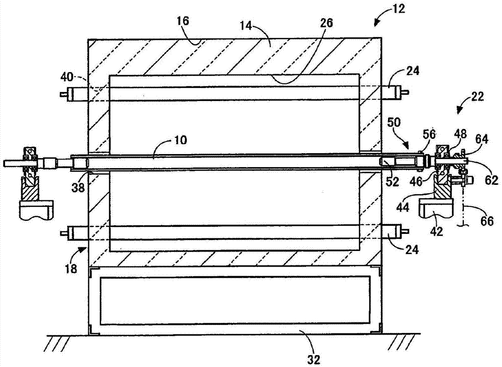
[0039] figure 1 It is a side view of the continuous conveyance type heating furnace 12 provided with the conveyance roller 10 for heating furnaces which concerns on one Example of this invention. figure 2 yes figure 1 The II-II arrow sectional view of the continuous conveyor heating furnace 12. The continuous conveyor heating furnace 12 is provided with: a heat insulating material 14 for keeping the inside of the furnace at a high temperature; The conveying roller 10 for heating furnace that is conveyed from one end of the longitudinal direction of the furnace body 18 to the other end; the conveying roller support device 22 that rotatably supports the two ends of the conveying roller 10 for heating furnace; The rotatably supported heating furnace uses a roller driving device (not shown) that rotates and drives the conveyor roller 10 ; and a vertically elongated heater 24 that heats the inside of the furnace body 18 to a high temperature. The furnace body 18 has: a furnace ...
experiment example
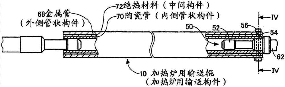
[0048] First, test samples No.1-N0.4 of the conveying roller 10 for a heating furnace were manufactured from a ceramic pipe 70, a metal pipe 68, and an insulating material 72 in such a manner as to satisfy the conditions in Table 1, and applied to a continuous conveying type heating furnace 12. Among them, the ceramic tube 70 is made of silicon carbide, and is a ceramic tube formed by an outer diameter of 34 mm and an inner diameter of 24 mm; The metal pipe 68 with variously changed intervals on the peripheral surface; the heat insulating material 72 is the heat insulating material 72 whose thickness is variously changed so as to fill the interval between the ceramic pipe 70 and the metal pipe 68 . The nickel alloy described as the material of the metal pipe constituting the test sample No. 4 is, for example, a solid solution strengthening type having a composition of 72% by mass of Ni, 14 to 17% by mass of Cr, and 6 to 10% by mass of Fe. Nickel-based heat-resistant alloys. N...
Embodiment 2
[0058] Next, another embodiment of the present invention will be described. In addition, in the following examples, the same code|symbol is attached|subjected to the part which is substantially the same as the above-mentioned example, and detailed description is abbreviate|omitted.
[0059] Figure 5 It is a side view illustrating a batch heating furnace 76 to which a furnace conveyor roller 74 according to another embodiment of the present invention is applied, Figure 6 yes Figure 5 The Ⅵ-Ⅵ arrow sectional view of the batch heating furnace 76 in Figure 7 yes Figure 6 The VII-VII arrow sectional view of the batch heating furnace 76 in FIG. The batch heating furnace 76 is composed of the following parts: a furnace body 78 composed of a heat insulating material 14 and a shell 16 covering the heat insulating material 14; The object to be heated 80 is transported in one direction to the prescribed position for heat treatment and transported from the prescribed position to...
PUM
 Abstract
Description
Claims
Application Information
 - R&D Engineer
- R&D Manager
- IP Professional
- Industry Leading Data Capabilities
- Powerful AI technology
- Patent DNA Extraction
Browse by: Latest US Patents, China's latest patents, Technical Efficacy Thesaurus, Application Domain, Technology Topic, Popular Technical Reports.
© 2024 PatSnap. All rights reserved.Legal|Privacy policy|Modern Slavery Act Transparency Statement|Sitemap|About US| Contact US: help@patsnap.com