
Electrical discharge machining device

A processing device, electric spark technology, applied in the direction of electric processing equipment, accessory devices, metal processing equipment, etc., can solve the problems that affect the processing accuracy and surface roughness, troublesome cleaning, etc., achieve stable quantity, easy export and cleaning, cleaning convenient effect

Inactive Publication Date: 2015-03-25
CHONGQING SHUAICHANG MACHINE MFG
View PDF0 Cites 3 Cited by
  • Summary
  • Abstract
  • Description
  • Claims
  • Application Information

AI Technical Summary

Problems solved by technology

The biggest problem with existing EDM devices is that during the process of electric erosion, the vaporized metal material of the workpiece will be thrown into the EDM fluid and condensed into tiny particles. Between the electrode and the workpiece, it will affect the machining accuracy and surface roughness, so it needs to be cleaned in time
However, these particles are suspended in the processing fluid, and it is very troublesome to clean up

Method used


Image

  • Electrical discharge machining device

Examples


Embodiment Construction

[0012] Below in conjunction with accompanying drawing and specific embodiment the present invention will be described in further detail:

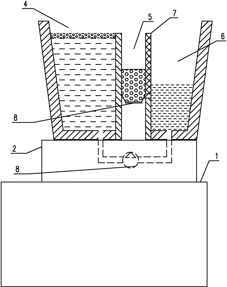
[0013] Such as figure 1 As shown, an electric discharge machining device includes a machine tool 1 and a workbench 2 positioned on the machine tool 1. The workbench 2 is provided with an electrode groove; the electrode groove includes a tank body, and two longitudinal partitions 3 are arranged in the tank body. The height of the separator 3 is lower than the height of the electrode tank wall, and the tank body is divided into a working tank 4, a particle collection tank 5 and a liquid storage tank 6, the particle collection tank 5 is located between the working tank 4 and the liquid storage tank 6, and the particle collection tank 5 and the height of the partition 3 between the working tank 4 is two-thirds of the wall of the electrode tank; The bottom is located at one-half of the height of the partition 3, and the bottom is also provided ...


PUM


Abstract

The invention relates to the field of electrical discharge machining, in particular to an electrical discharge machining device. The electrical discharge machining device comprises a machine tool and a working table located on the machine tool. An electrode bath is arranged on the working table and comprises a bath body, two longitudinal partition plates are arranged in the bath body to divide the bath body into a working bath body, a particulate matter collecting bath body and a liquid storage bath body, the particulate matter collecting bath body is located between the working bath body and the liquid storage bath body, and the partition plate between the particulate matter collecting bath body and the working bath body is lower than the bath wall of the electrode bath body; a filtering film is arranged on the partition plate between the particulate matter collecting bath body and the liquid storage bath body, the bottom of the particulate matter collecting bath body is higher than the bottom of the working bath body and the bottom of the liquid storage bath body, and a communicating pipe is further arranged between the working bath body and the liquid storage bath body and provided with a hydraulic pump; electrical discharge machining liquid is arranged in the working bath body, and the liquid level of the electrical discharge machining liquid is the same as the partition plates in height; the liquid level of the electrical discharge machining liquid in the liquid storage bath body is not higher than the bottom of the particulate matter collecting bath body. By means of the technical scheme, the electrical discharge machining device has the advantage that electric corrosion particular matter can be conveniently removed.

Description

technical field [0001] The invention relates to the field of electrical discharge machining, in particular to an electrical discharge machining device. Background technique [0002] EDM can process any hard, brittle, soft and high-melting conductive materials, such as hardened steel, hard alloy, etc. There is no cutting deformation during processing, which is beneficial to the processing of small holes, thin walls, narrow grooves, and various complex cross-section holes and cavity parts. Rough machining, semi-finishing machining and finishing machining are connected on the machine tool; at the end of the pulse discharge duration, the workpiece processing surface is almost not affected; direct electric machining is convenient for automatic control and processing automation. [0003] The existing EDM device is mainly composed of three parts: mechanical system, servo system and high-frequency power supply. The mechanical system includes a machine tool, a workbench on the machi...

Claims


Application Information

Patent Timeline
IPC IPC(8): B23H1/00B23H11/00
CPCB23H1/00B23H1/10
Inventor 丁丽霞
Owner CHONGQING SHUAICHANG MACHINE MFG
Learn More