


Quick Research
Generate reliable direction feasibility study reports for your R&D in just a few steps.

Technical Q&A
Discover and master advanced knowledge NOW. Basics, ideas, possibilities, all at once.

Find Solutions
As an expert in R&D theories, this can generate solutions to your technical problems instantly.

Evaluate Feasibility
Analyze your overall solution with one click, know your potential R&D risks in advance.

Monitor Landscape
Get weekly tech updates, stay abreast of the latest tech innovations and key insights.
A method for controllable growth of carbon nanotube bundles in the horizontal direction of the substrate
A carbon nanotube bundle, horizontal direction technology, applied in nanotechnology, nanotechnology, nanostructure manufacturing and other directions, can solve the problems of complex template processing, inability to meet nanoelectronic devices, destroying carbon nanotube structures, etc. Versatile, easy-to-integrate effects
- Summary
- Abstract
- Description
- Claims
- Application Information
AI Technical Summary
Problems solved by technology
Method used
Image

Examples
Embodiment 1
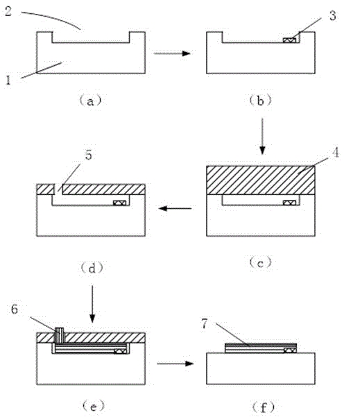
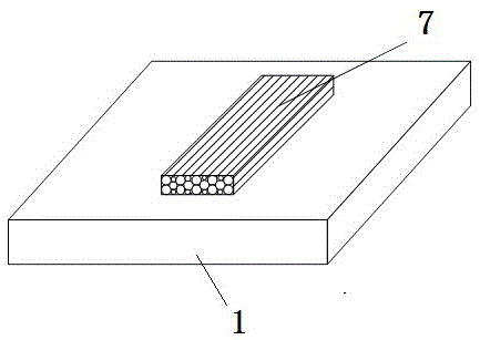
[0045] (1) Prepare the first silicon wafer 1, clean it with conventional semiconductor cleaning process, dry it, and use photolithography process and ion reaction etching process to process a 10 micron long and wide carbon nanotube bundle on the surface of the silicon wafer. 2 microns, horizontal micro-nano channel 2 with a depth of 2 microns;
[0046] (2) Spin-coat a layer of AZ4620 photoresist on the surface of the first silicon wafer 1 with a thickness of 3 microns by using a coating machine, expose and develop the catalytic film deposition window, and use the electron beam evaporation process on the surface of the first silicon wafer Sequentially deposit a 6-nm-thick Al2O3 layer and a 1-nm-thick Co layer to form the catalytic film 3, remove the photoresist, and remove the catalytic film on the photoresist along with it, leaving the micro-nano channel 2 after patterning The catalytic membrane 3, the size of the catalytic membrane is 2 microns in width and 2.2 microns in len...
Embodiment 2
[0052] (1) Prepare the quartz sheet 1, clean it with conventional semiconductor cleaning process, dry it, use photolithography process and ion reaction etching process to process 10 microns in length and 2 microns in width at the position where carbon nanotube bundles need to be grown on the surface of the quartz plate, Horizontal micro-nano channel 2 with a depth of 2 microns;
[0053] (2) Spin-coat a layer of AZ4620 photoresist on the surface of the quartz plate 1 with a homogenizer, with a thickness of 3 microns, expose and develop the catalytic film deposition window, and deposit 10 nanometers of photoresist on the surface of the quartz plate sequentially using an electron beam evaporation process. The Al2O3 layer and the 2 nanometer thick Fe layer form the catalytic film 3, remove the photoresist, and the catalytic film on the photoresist is removed together thereupon, leaving the patterned catalytic film 3 in the micro-nano channel 2, catalyzed The film size is 2 microns...
Embodiment 3
[0059] (1) Prepare a piece of aluminum oxide sheet 1, clean it with conventional semiconductor cleaning technology, dry it, use photolithography technology and ion reaction etching technology to process a 10 micron long and wide carbon nanotube bundle on the surface of the aluminum oxide sheet 2 microns, horizontal micro-nano channel 2 with a depth of 2 microns;
[0060] (2) Spin-coat a layer of AZ4620 photoresist on the surface of alumina sheet 1 with a coater, with a thickness of 3 microns, expose the catalytic film deposition window by exposure and development, and deposit 12 nanometers on the surface of alumina sheet sequentially using electron beam evaporation process A thick Al2O3 layer and a 3nm-thick Ni layer form the catalytic film 3, the photoresist is removed, and the catalytic film on the photoresist is removed together, leaving the patterned catalytic film 3 in the micro-nano channel 2 , the size of the catalytic membrane is 2 microns wide and 2.5 microns long;
...
PUM
| Property | Measurement | Unit |
|---|---|---|
| thickness | aaaaa | aaaaa |
| thickness | aaaaa | aaaaa |
Abstract
Description
Claims
Application Information
 - R&D Engineer
- R&D Manager
- IP Professional
- Industry Leading Data Capabilities
- Powerful AI technology
- Patent DNA Extraction
Browse by: Latest US Patents, China's latest patents, Technical Efficacy Thesaurus, Application Domain, Technology Topic, Popular Technical Reports.
© 2024 PatSnap. All rights reserved.Legal|Privacy policy|Modern Slavery Act Transparency Statement|Sitemap|About US| Contact US: help@patsnap.com