
A cathode with a microporous membrane structure

一种微孔膜、微孔滤膜的技术,应用在电气元件、等离子体等方向,能够解决阴极易被烧蚀等问题,达到提高生产效率、克服容易被烧蚀、节约生产成本的效果

Active Publication Date: 2017-07-28
XINGHUA GOLDEN PEACOCK IND DEV CO LTD
View PDF8 Cites 0 Cited by
  • Summary
  • Abstract
  • Description
  • Claims
  • Application Information

AI Technical Summary

Problems solved by technology

[0005] The purpose of the present invention is to provide a cathode of a microporous membrane structure and a plasma pyrolysis water spray gun, which can be used in gasifiers of domestic garbage, industrial organic waste gasifiers or coal gasification devices to improve the gasification rate and Improve the quality of synthesis gas, and make the cathode not easy to be ablated, overcome the shortcomings of the existing plasma torch that the cathode is easy to be ablated, so as to prolong the service life of the plasma torch, improve production efficiency and save production costs

Method used


Image

  • A cathode with a microporous membrane structure
  • A cathode with a microporous membrane structure
  • A cathode with a microporous membrane structure

Examples


Embodiment 1

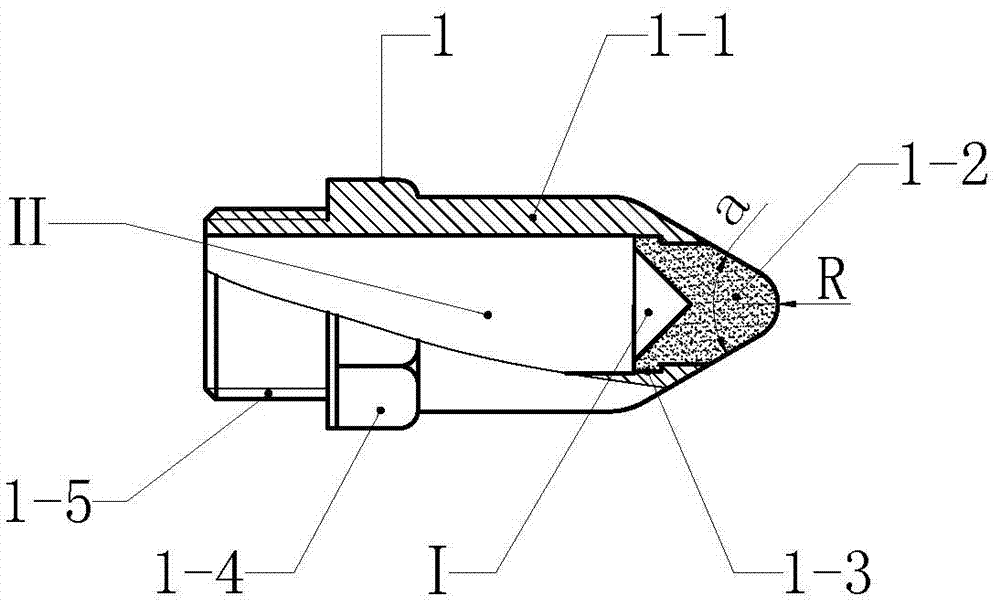
[0016] Example 1 figure 1 In the illustrated embodiment, a cathode of a microporous membrane structure is composed of a microporous membrane cathode head 1-2 and a cathode sleeve 1-1, wherein the microporous membrane cathode head 1-2 is a microporous filter sintered with metal powder. Membrane structure, the micropores between the metal powders constitute the filtration channel of water molecules, the center of the rear end of the microporous membrane cathode head 1-2 has a conical groove I, the groove I constitutes the water source inlet, the microporous membrane cathode head 1-2 There is a flange 1-3 outside the rear end of 2, and the flange 1-3 constitutes the axial limit structure of the microporous membrane cathode head 1-2, and the head of the microporous membrane cathode head 1-2 shrinks from the rear to the front The cone structure, its cone angle a is 60 °, the head end of the microporous film cathode head 1-2 is an arc-shaped structure, and its arc radius R is 5mm; t...

Embodiment 2

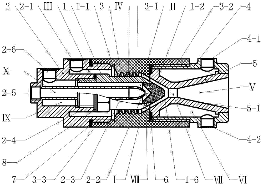
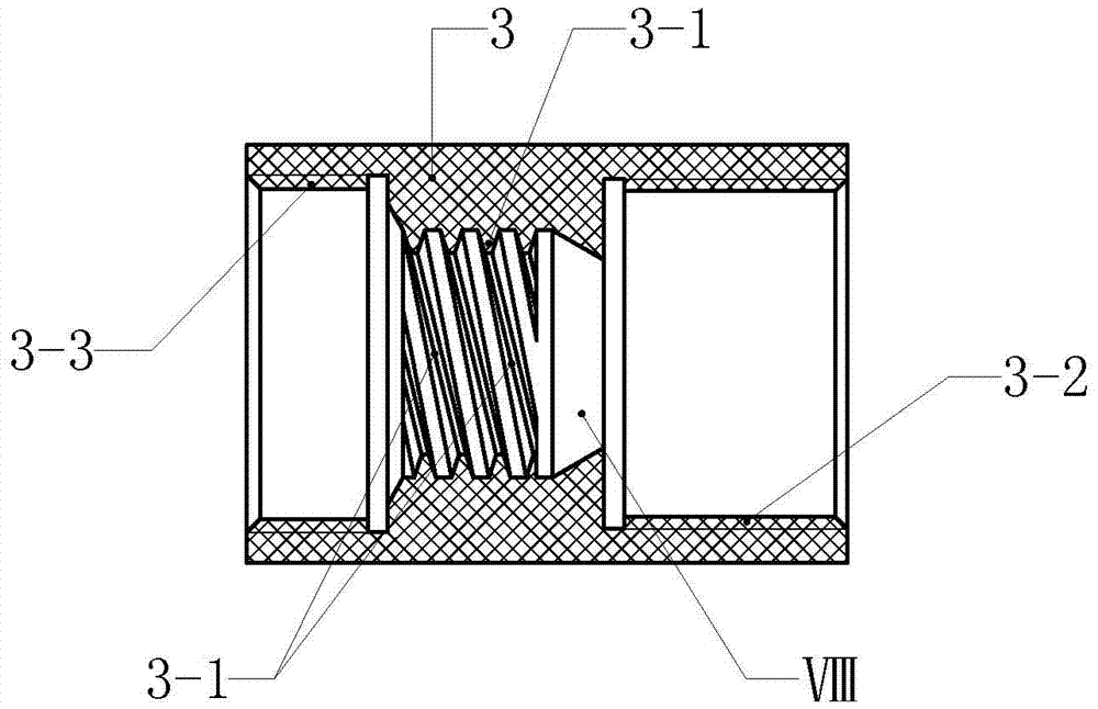
[0017] Example 2 figure 2 In the illustrated embodiment, the plasma pyrolysis water spray gun is composed of a backseat 2, a cathode 1, a spiral deflector 3, an anode cover 4 and an anode 5, wherein the backseat 2 is a rotary structure, and the rotation of the backseat 2 There are water supply diversion pipe 2-3 and cathode connecting rod 2-4 in the body, and cathode connecting rod 2-4 is a circular pipe body structure, and water supply diversion pipe 2-3 and cathode connecting rod 2-4 are arranged coaxially, and water supply guide The flow tube 2-3 is inside the tube of the cathode connecting rod 2-4, and the space in the tube of the water supply diversion tube 2-3 constitutes the cooling water supply channel X, and the outer wall of the water supply diversion tube 2-3 and the inner wall of the cathode connecting rod 2-4 The space in the space constitutes the cooling water return channel Ⅸ, and the water outlet of the water supply diversion pipe 2-3 is a narrow nozzle struct...


PUM


Abstract

A cathode with a microporous membrane structure and a plasma pyrolysis water spray gun, relating to a plasma spray gun, the cathode is composed of a microporous membrane cathode head and a cathode sleeve, and the micropores of the microporous membrane cathode head form a filtration channel for water molecules , the microporous membrane cathode head is embedded in the wall body at the front of the cathode sleeve, and the head of the microporous membrane cathode head protrudes from the front end of the cathode sleeve; the plasma pyrolysis water spray gun consists of a rear seat, a cathode, a spiral deflector, The anode sleeve and the anode are composed of a water supply guide pipe and a cathode connecting rod in the rotator of the rear seat, and a spiral guide rib is provided in the rotator of the spiral deflector. The anode is a venturi nozzle structure, and the anode is installed in an embedded manner. In the anode sleeve, the space between the outer wall of the anode and the inner wall of the anode sleeve constitutes a cooling water jacket, the cathode is connected to the front end of the cathode connecting rod of the rear seat, the rear end of the spiral deflector is installed on the rear seat, and the anode sleeve and the anode are installed on the spiral front end of deflector. The invention utilizes the latent heat of vaporization of water to quickly absorb the heat of the cathode head, so that the cathode is not easy to be ablated.

Description

technical field [0001] The invention relates to plasma equipment, in particular to a plasma spray gun. Background technique [0002] At present, plasma technology has been widely used, industrially used in plasma ignition, plasma spraying, metal smelting, plasma heating to manufacture nanomaterials, cutting, waste incineration and waste treatment, etc. The plasma treatment method is very different from the general method. Plasma is a state formed under the ionosphere or discharge phenomenon. With the discharge phenomenon, excited atoms, excited molecules, dissociated atoms, free atomic groups, Active chemicals of groups of atoms or molecular ions and their reactions resulting from collisions with other chemicals. In the plasma generator, the discharge effect causes the working gas molecules to lose the outer electrons and form an ion state, which generates high temperature through mutual collision, and the temperature can reach more than tens of thousands of degrees. [00...

Claims


Application Information

Patent Timeline
Patent Type & Authority Patents(China)
IPC IPC(8): H05H1/34
CPCH05H1/28H05H1/34H05H1/3436
Inventor 周开根
Owner XINGHUA GOLDEN PEACOCK IND DEV CO LTD
Learn More