
High-efficiency and long-life stranded electrode wire for wire electric discharge cutting

A technology of electric discharge wire and electrode wire, which is applied in the direction of electrode manufacturing, electric processing equipment, metal processing equipment, etc., can solve the problems of poor chip removal ability, less working fluid, and the cost of easy wire breakage, so as to reduce the probability of wire breakage, Improve the cutting speed and solve the effect of strength

Active Publication Date: 2016-07-06
NANJING UNIV OF AERONAUTICS & ASTRONAUTICS
View PDF6 Cites 0 Cited by
  • Summary
  • Abstract
  • Description
  • Claims
  • Application Information

AI Technical Summary

Problems solved by technology

[0004] The purpose of the present invention is to solve the problem of less working fluid brought into the gap by the wire EDM electrode wire in the existing high-speed reciprocating wire cutting or low-speed unidirectional wire EDM, poor chip removal ability, easy wire breakage and high-speed reciprocating wire cutting. In general, only materials with high melting points such as molybdenum or tungsten can be used to produce high cost. A twisted electrode wire that can not only carry the working fluid into the cutting gap, but also discharge the erosion products out of the processing area in time

Method used


Image

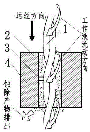
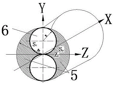
  • High-efficiency and long-life stranded electrode wire for wire electric discharge cutting
  • High-efficiency and long-life stranded electrode wire for wire electric discharge cutting
  • High-efficiency and long-life stranded electrode wire for wire electric discharge cutting

Examples


Embodiment Construction

[0018] Below in conjunction with accompanying drawing and example the present invention will be further described

[0019] like Figure 1-2 shown.

[0020] A twisted electrode wire for wire electric discharge cutting, which consists of two or more electrode wires that are twisted by a twisting mechanism to form a twist-like structure, and a wire that can carry working fluid and erode is formed in the depression of the twist-like structure. In addition to the chip space where the product is taken out of the processing space, the raised part of the twist-shaped structure is more likely to form a discharge point, which improves the explosive erosion ability. The material of each electrode wire can be the same or different. When the material is the same, the discharge rate can be the same or different. The diameter of each electrode wire can be the same or different. The diameter of the same electrode wire can also be the same or different. .

[0021] exist figure 1 In the pro...


PUM


Abstract

An efficient long-service-life stranded electrode wire for an EDM wire is characterized by being formed by stranding at least two electrode wire bodies. Concave cavity grooves and convex discharging joint points are formed on the surfaces of the stranded electrode wire bodies. The concave cavity grooves are not only containing spaces for a working solution but also discharging spaces for inter-electrode corrosion removal products. In addition, feeding of the working solution and the discharging of the corrosion removal products are respectively performed in a spiral mode, and then the inter-electrode cooling effect and the deionization ability are improved. The discharging joint points can form regular discharging, and a discharging pulse interval can be indirectly prolonged. As the surfaces of the electrode wire bodies are provided with the concave parts which serve as the chip containing spaces, the working solution can be fed into inter-electrode in a promoted mode; meanwhile the discharging of the inter-electrode corrosion removal products is accelerated, so that the inter-electrode discharging conditions are improved; due to the regular convex points on the surfaces of the stranded electrode wire bodies, the discharging rule is easier to control. Accordingly, machining efficiency can be enhanced, and surface quality can be improved. Besides, the volume of the chip containing spaces of the stranded electrode wire bodies can be controlled according to the diameter of the electrode wire bodies and the pitch of the stranded wire bodies.

Description

technical field [0001] The invention relates to a wire electric discharge processing technology, in particular to an electrode wire for wire electric discharge cutting, specifically a wire electric discharge wire cutting which can be applied to high-speed reciprocating wire electric discharge and low-speed one-way wire cutting. High-efficiency and long-life stranded electrode wire for wire-cut electric discharge machining. Background technique [0002] The working principle of wire electric discharge cutting is: the wire electrode running at a certain speed breaks down the working fluid medium under the condition of power on, so as to discharge the conductive material to realize the discharge erosion of the material. Therefore, the wire electrode is the wire electric discharge cutting processing equipment. Indispensable part. [0003] At present, the electrode wire is mainly divided into two categories, one is the electrode wire used on the high-speed reciprocating wire ele...

Claims


Application Information

Patent Timeline
Patent Type & Authority Patents(China)
IPC IPC(8): B23H7/08
Inventor 刘志东邱明波田宗军沈理达
Owner NANJING UNIV OF AERONAUTICS & ASTRONAUTICS
Learn More