
Nickel slag grinding system and production process thereof

A technology for nickel slag powder and nickel slag, which is applied in the fields of resource recycling and environmental protection, can solve the problems of high abrasiveness and abrasiveness of nickel slag, large consumption of steel balls in ball mills, and high power consumption in ball mill grinding, and can save energy. The electric effect is obvious, the land utilization rate is improved, and the structure is simple and reliable.

Active Publication Date: 2014-07-30
中材(天津)粉体技术装备有限公司 +1
View PDF8 Cites 14 Cited by
  • Summary
  • Abstract
  • Description
  • Claims
  • Application Information

AI Technical Summary

Problems solved by technology

The nickel slag grinding equipment in the prior art mainly adopts cone crusher and ball mill. After the cone crusher crushes the nickel slag to a certain particle size, the ball mill is used for final grinding operation. The abrasiveness is relatively high, resulting in high grinding power consumption of the ball mill, up to about 90 degrees / ton, and the production capacity is small, and the steel ball consumption of the ball mill is also large

Method used


Image

  • Nickel slag grinding system and production process thereof

Examples


Embodiment

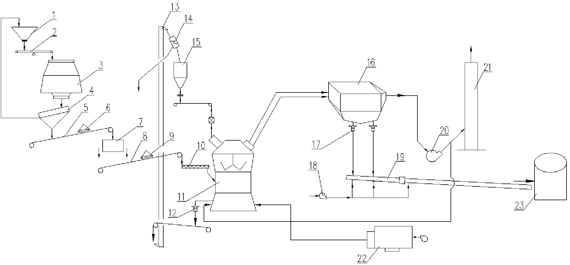
[0022] Example: see figure 1 As shown, realize the nickel slag grinding production system of the present invention's nickel slag grinding production process, its core equipment mainly includes feeding bin 1, quantitative feeder 2, column mill 3, vibrating screen 4, belt conveyor 5, Powerful magnetic separator 7, nickel slag vertical mill 11, dry magnetic separator 14, bag filter 16, main exhaust fan 20 and hot blast stove system 22.

[0023] The raw nickel slag transported by the transport vehicle is sent into the feeding bin 1 by the loader, and a quantitative feeder 2 is installed between the outlet of the feeding bin and the inlet of the column mill 3, and the vibrating screen 4 is installed in the column mill. The first belt conveyor 5 is installed under the machine 3 and the vibrating screen, the first permanent magnet self-unloading iron remover 6 is installed on the top of the first belt conveyor, and the powerful magnetic separator 7 is installed at the outlet of the f...


PUM

PropertyMeasurementUnit
Graininessaaaaaaaaaa
Granularityaaaaaaaaaa

Abstract

The invention relates to a nickel slag grinding system which is characterized by mainly comprising a feeding bin, a quantitative feeding machine, a column mill vibrating screen, a belt conveyor, a strong magnetic separator, a nickel slag vertical mill, a dry magnetic separator, a bag type dust collector, a main exhaust blower and a hot blast heater system. Nickel slag with the water content being not more than 5 percent and the granularity being less than 60mm is sent to the column mill to be ground by using the nickel slag grinding system, so that fine powder with the water content being above 90 percent and the granularity being below 5mm is obtained, the fine powder is subjected to iron separation through the strong magnetic separator after being screened, and is dried and ground in the nickel slag vertical mill after being subjected to iron removal. Meanwhile, after large particles containing iron are thrown out by a millstone, and are fed into the mill again after being subjected to iron removal through the dry magnetic separator. Finally, after multiple times of circulating grinding, a finished nickel slag micropowder product with a specific surface area of 4200-4500 cm<2> / g is obtained, and the finished product passing through the bag type dust collector is sent to a finished product library through an air conveying chute, and waste gas is discharged into atmosphere through a chimney. The nickel slag grinding system has the advantages of large yield, high grinding efficiency, low use cost and operation cost, remarkable electricity saving effect, and increasing of economic benefits.

Description

technical field [0001] The invention belongs to the technical field of resource recycling and environmental protection, and relates to a nickel slag treatment technology in the metallurgical industry, in particular to a nickel slag grinding system and a production process thereof. Background technique [0002] Nickel slag is one of the main waste residues of nickel-iron alloy production enterprises, and its discharge is about 6-10 times that of nickel-iron alloy production. It is estimated that the discharge of nickel slag in my country in 2015 will be more than 100 million tons. Slag will occupy more and more land, pollute the environment, cause waste of resources, and further affect the sustainable development of the nickel-iron alloy smelting industry. At present, the effective treatment method is to grind the nickel slag finely, then mix it into cement, and use it as a mixture of building materials. The nickel slag grinding equipment in the prior art mainly adopts cone c...

Claims


Application Information

Patent Timeline
IPC IPC(8): B02C21/00B02C23/00B02C23/02B02C23/14B03C1/02
Inventor 石光申占民王庆利
Owner 中材(天津)粉体技术装备有限公司
Learn More