
Electromagnetic modulation fusion emitting device

A launching device and electromagnetic technology, applied in the field of three-dimensional molding manufacturing, can solve the problems of high cost, unfavorable health of workers, low strength, etc., and achieve the effects of excellent manufacturing cost and durability, saving powder cleaning process, and improving structural performance.

Inactive Publication Date: 2014-06-18
曹炜喜
View PDF8 Cites 27 Cited by
  • Summary
  • Abstract
  • Description
  • Claims
  • Application Information

AI Technical Summary

Problems solved by technology

The disadvantages are: sometimes the molded parts will form micropore defects due to insufficient powder melting, the required powder materials are expensive, the use of materials has dust pollution problems, and the high-power lasers used are expensive and not durable enough
The disadvantage is: the material is heated by resistance wire, and the molding material used is generally thermoplastic, wax or artificial rubber with a low melting point. The molding material is mainly non-metal, and the strength is not high, so it is difficult to directly form metal parts
Among these 3D printing and molding manufacturing technologies, only selective laser sintering can directly realize the 3D molding of metal parts. It has been used in high-end manufacturing fields, but it cannot be widely used in traditional industries, which limits the development of three-dimensional molding manufacturing technology. At the same time, the work of removing excess powder after parts are made also has a negative impact on workers' health.

Method used


Image

  • Electromagnetic modulation fusion emitting device
  • Electromagnetic modulation fusion emitting device

Examples


Embodiment Construction

[0020] The electromagnetic modulation melting emission device of the present invention will be further described below in conjunction with the accompanying drawings and specific embodiments:

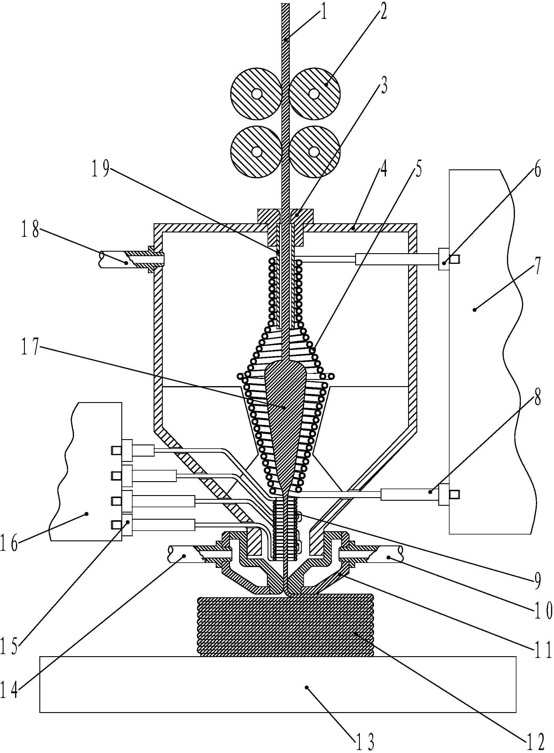
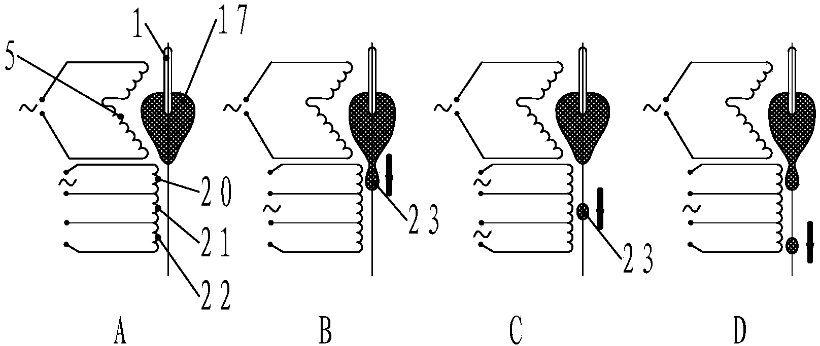
[0021] figure 1 It is a schematic diagram of the structure of the electromagnetic modulation melting emission device of the present invention, figure 2 It is a principle diagram of material melting injection in the electromagnetic modulation melting emission device of the present invention. In the figure, the electromagnetic modulation melting emission device includes an induction heating coil 5, a three-phase linear induction heating coil 9 and a nozzle 11. Directly below the heating coil 5, the periphery of the induction heating coil 5 is provided with a support cylinder 4, the lower end of the support cylinder 4 is connected to the nozzle 11, the upper end of the support cylinder 4 is provided with a wear-resistant bushing 3, and the inner hole of the lower end of the wear-resistant...


PUM


Abstract

The invention discloses an electromagnetic modulation fusion emitting device which comprises an induction heating coil, a three-phase linear induction heating coil and a spray nozzle, wherein the three-phase linear induction heating coil is arranged under the induction heating coil; a support cylinder is arranged at the periphery of the induction heating coil; the lower end of the support cylinder is connected with the spray nozzle; two ends of the induction heating coil are connected to an alternating power supply; the three-phase linear induction heating coil is arranged into a three-phase four-wire system circuit structure; four ends of the three-phase linear induction heating coil are respectively connected to a three-phase pulse alternating power supply. A levitation melting technology and a linear induction motor principle technology adopted by the electromagnetic modulation fusion emitting device are both common electromagnetic induction technologies in a traditional industry, the process is mature, the manufacturing cost and the durability are superior to those of a selected laser sintering (SLS) technology adopting a high-power laser, and the electromagnetic modulation fusion emitting device is more suitable for applicable in the traditional industry.

Description

technical field [0001] The invention relates to a three-dimensional molding manufacturing technology, and more specifically relates to an electromagnetic modulation melting emission device in the rapid manufacturing of fusion deposition. Background technique [0002] Among the existing three-dimensional modeling manufacturing technologies, the most widely used are selective laser sintering (SLS) and fused deposition modeling (FDM). Among them, the selective laser sintering technology is to first use the software to "cut" the 3D digital model of the part into several planes, which forms many sections. After the 3D model is sliced, in a container, one can be dropped. Firstly, the surface of the material roller is covered with a layer of material powder to be sintered. These powders can be made very fine, and then the high-power laser is controlled by software to select the bottom 3D slice shape data to start sintering. Then the platform moves down, and the material roll is la...

Claims


Application Information

Patent Timeline
IPC IPC(8): B22F3/115
Inventor 曹炜喜
Owner 曹炜喜
Learn More