Device and method for manufacturing aerated concrete blocks with holes and grooves in core pulling mode
A technology of aerated concrete and blocks, which is applied in the direction of manufacturing tools, ceramic molding machines, auxiliary parts of molds, etc., can solve the problem that the core pulling device does not have any technical solutions, and achieve high production efficiency, improve efficiency, and shorten time. Effect
- Summary
- Abstract
- Description
- Claims
- Application Information
AI Technical Summary
Problems solved by technology
Method used
Image
Examples
Embodiment 1
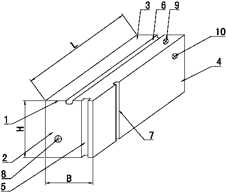
[0039] combine figure 1 , figure 2 , Figure 4~6 , a device for manufacturing air-entrained concrete blocks with holes and grooves by core pulling, including a mandrel 31, which is fixed inside the mold 20 through a fixed frame 30, and the installation position of the mandrel 31 is the same as that on the block 1 The positions of the inner hole and the groove are corresponding, and the fixed frame 30 is connected with the mold 20 through the positioning bracket 19, and the fixed frame 30 is provided with a locking pair for locking the mandrel 31.
[0040] Specifically, the fixed frame 30 is erected above the mold 20, the upper layer of the fixed frame 30 is fixed with an upper positioning backing plate 32, and the lower layer is fixed with a lower positioning backing plate 34, and an intermediate pressure is set between the corresponding pair of positioning backing plates. Tightening plate 33, the three form a group of locking pairs that fix a mandrel 31; each group of lock...
Embodiment 2
[0061] combine figure 1 , Figure 7 , Figure 4~6, in this embodiment, specifically: in the direction of 4200mm of the embryo body 12, the L=600mm length of the block 1 is cut out from the transverse separation surface 14; The H=240mm height of the block 1; on the 600mm direction of the embryo body 12, the B=200mm width of the block 1 is cut out from the vertical vertical separation surface 15; in the 600mm direction of the embryo body 12, the On the side, a side groove 7 is prepared, and the cross-sectional size of the groove is a rectangle of 40mm×40mm and four corners R3mm.
[0062] The difference between this embodiment and embodiment 1 is:
[0063] Mandrel 31 selects the special-shaped thin-walled steel pipe of 80mm * 40mm;
[0064] Cutting can adopt the method in the patent of the applicant whose application number is 201310203569.3: "Method for making autoclaved aerated concrete components by cutting steel wires in mesh arrangement" to complete the cutting of the lo...
Embodiment 3
[0067] combine figure 1 , Figure 8 , in this embodiment, specifically: in the direction of 4200mm of the embryo body 12, the L=600mm length of the block 1 is cut out from the transverse separation surface 14; The B=200mm width of the block 1; in the direction of 600mm of the embryo body 12, the H=240mm height of the block 1 is cut out from the vertical vertical separation surface 15; the block 1 has an inner diameter of Φ25 perpendicular to the top surface hole.
[0068] The differences in this example are:
[0069] Mandrel 31 selects Φ25mm thin-walled steel pipe;
[0070] Cutting can adopt the method in the patent of the applicant whose application number is 201310203569.3: "Method for making autoclaved aerated concrete components by cutting steel wires in mesh arrangement" to complete the cutting of the longitudinal vertical separation surface 15;
[0071] The positioning position of the mandrel 31 needs to be recalculated, and the fixed frame 30 needs to be assembled o...
PUM
 Abstract
Description
Claims
Application Information
 - R&D
- Intellectual Property
- Life Sciences
- Materials
- Tech Scout
- Unparalleled Data Quality
- Higher Quality Content
- 60% Fewer Hallucinations
Browse by: Latest US Patents, China's latest patents, Technical Efficacy Thesaurus, Application Domain, Technology Topic, Popular Technical Reports.
© 2025 PatSnap. All rights reserved.Legal|Privacy policy|Modern Slavery Act Transparency Statement|Sitemap|About US| Contact US: help@patsnap.com


