
Method for virtually arranging monitoring camera of construction site based on BIM technology

A surveillance camera and construction site technology, which is applied in the field of virtual arrangement of construction site surveillance cameras based on BIM technology, can solve the problems of camera blocking, multiplication of effort, waste of materials, etc., so as to reduce unnecessary waste, reduce management costs, and speed up installation. Effect

Active Publication Date: 2017-07-14
CHINA CONSTR EIGHT ENG DIV CORP LTD
View PDF6 Cites 14 Cited by
  • Summary
  • Abstract
  • Description
  • Claims
  • Application Information

AI Technical Summary

Problems solved by technology

The traditional method of arranging the monitoring system has great limitations, because the commonly used cameras are fixed at a certain height and facing a specified direction, and the range of imaging is limited. This kind of picture cannot be specifically simulated by the human brain. In addition, during the construction process, as the main structure gradually rises from the ground, it will block some of the objects originally monitored by the cameras, and the brains of one or two unit engineers may still be able to imagine it. If there are more unit projects Coupled with the complexity of the surrounding environment, there are more and more blind spots and obstacles. For this situation, the usual method is to add more surveillance cameras to make up for it. Since it is impossible to specifically simulate the imaging conditions and field of view height of the surveillance cameras, the layout The final effect is often unsatisfactory, resulting in twice the result with half the effort
Not to mention the waste of materials if the monitoring effect is not achieved, it also increases the maintenance cost in the process

Method used


Image

  • Method for virtually arranging monitoring camera of construction site based on BIM technology

Examples


Embodiment Construction

[0022] Embodiments of the present invention are described below through specific examples, and those skilled in the art can easily understand other advantages and effects of the present invention from the content disclosed in this specification. The present invention can also be implemented or applied through other different specific implementation modes, and various modifications or changes can be made to the details in this specification based on different viewpoints and applications without departing from the spirit of the present invention.

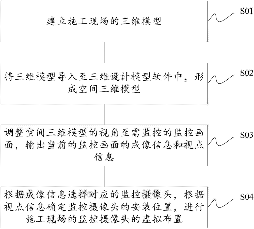
[0023] refer to figure 1 As shown, it is an operation flowchart of a method for virtual arrangement of monitoring cameras on a construction site based on BIM technology in the present invention. Such as figure 1 As shown, a kind of method of the present invention based on BIM technology mainly comprises the following steps to the virtual layout of construction site monitoring camera:

[0024] S01: Establish a 3D model of the constru...


PUM


Abstract

The invention discloses a method for virtually arranging a monitoring camera of a construction site based on a BIM technology. The method comprises the steps of building a three-dimensional model of the construction site; importing the three-dimensional model to three-dimensional design model software, thereby forming a spatial three-dimensional model; adjusting a view angle of the spatial three-dimensional model to a monitoring image needed to be monitored, and outputting imaging information and viewpoint information of the current monitoring image; and selecting a corresponding monitoring camera according to the imaging information, determining a mounting position of the monitoring camera according to the viewpoint information, and performing virtual arrangement of the monitoring camera of the construction site. According to the method, reasonable arrangement can be performed through the BIM technology; and the monitoring camera of the construction site is subjected to virtual and reasonable arrangement by utilizing a visualization characteristic and a simulation characteristic of the BIM technology, so that unnecessary waste of materials in a real mounting process is reduced, the mounting speed is increased, and the management cost is reduced.

Description

technical field [0001] The invention relates to a method for virtual arrangement of monitoring cameras on a construction site based on BIM technology, in particular to a method for arranging monitoring cameras at a construction site with large construction sites, many unit projects, and complex surrounding conditions of the projects. Background technique [0002] For the layout of the monitoring system on the construction site, the traditional layout method is to select the location of the monitoring camera by referring to the general layout plan and site survey and simulating the imagination in the brain. The traditional method of arranging the monitoring system has great limitations, because the commonly used cameras are fixed at a certain height and facing a specified direction, and the range of imaging is limited. This kind of picture cannot be specifically simulated by the human brain. In addition, during the construction process, as the main structure gradually rises f...

Claims


Application Information

Patent Timeline
IPC IPC(8): G06F17/50G06T17/00
CPCG06T17/00G06F30/13
Inventor 陈笑凯亓立刚崔爱珍
Owner CHINA CONSTR EIGHT ENG DIV CORP LTD
Learn More