
Miniature drill bit and machining method thereof

A micro-drill and drill-tip technology, which is applied in metal processing equipment, twist drills, drill accessories, etc., can solve the problems of space reduction, affecting hole position accuracy, and excessive heating of drill tips, so as to improve heat dissipation efficiency and improve replacement Thermal efficiency, the effect of improving heat dissipation efficiency

Active Publication Date: 2014-04-30
SHENZHEN JINZHOU PRECISION TECH
View PDF11 Cites 2 Cited by
  • Summary
  • Abstract
  • Description
  • Claims
  • Application Information

AI Technical Summary

Problems solved by technology

[0004] 1) Due to poor dust removal and excessive heating of the drill tip, the tool breaks
2) Poor hole position accuracy
[0006] The above design brings two problems: 1) The helical groove is non-symmetrical with respect to the rotation center, and the center of mass of the drill tip is too far away from the axis. 2) The length of the second helical groove is shorter than that of the first helical groove, and it is a blind groove. Chips are easy to accumulate in the blind groove, causing dry friction and heat with the hole wall. While the first helical groove undertakes excessive chip removal, the drilling machine The space for the vacuum cleaner to suck the air in the groove is further reduced, which affects the heat dissipation of the drill tip

Method used


Image

  • Miniature drill bit and machining method thereof
  • Miniature drill bit and machining method thereof
  • Miniature drill bit and machining method thereof

Examples


Embodiment 1

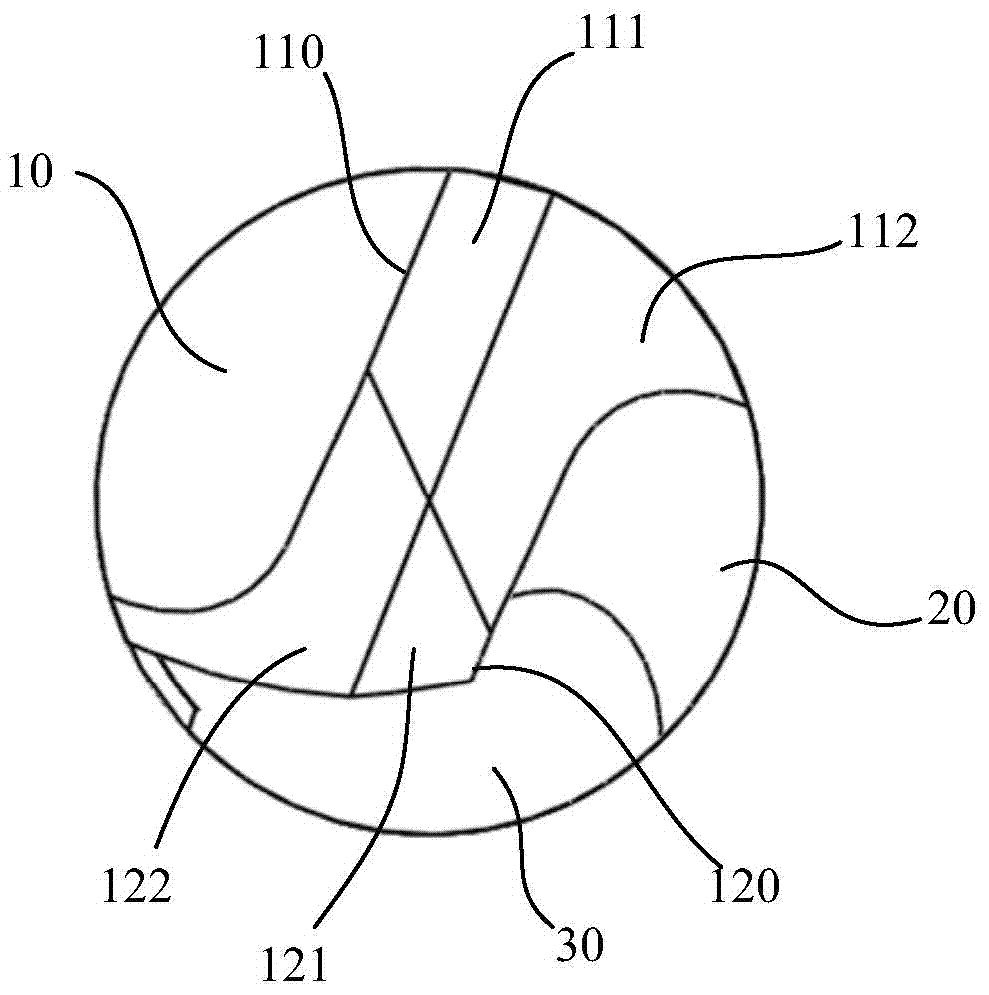
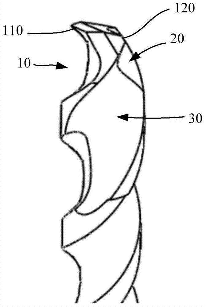
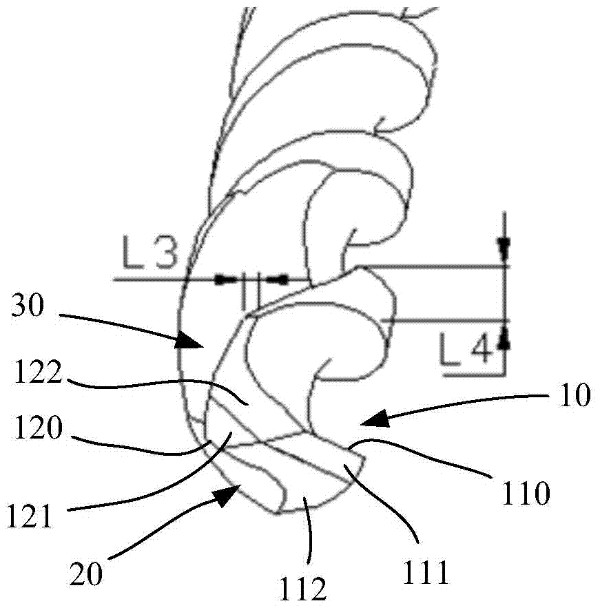
[0039] like Figure 1 to Figure 3 As shown, the micro drill includes: a first rake face 111, a first relief face 112, a second rake face 121, and a second flank 122 arranged at the drill point; The first helical groove 10 and the second helical groove 20 arranged symmetrically with the first helical groove, the first helical groove 10 intersects with the first rake face 111 to form a first cutting edge 110, the second The helical groove 20 intersects with the second rake face 121 to form a second cutting edge 120; and an offset groove 30 arranged at the front end region of the drill bit, as Figure 5 As shown, the offset groove 30 intersects with the second rake face 121, so that the length L1 of the second cutting edge 120 is smaller than the length L2 of the first cutting edge 110, and the offset groove 30 and the The second helical grooves 20 intersect. The depth of the offset groove 30 is greater than the depth of the second flute 20, which can expand the space of the of...

Embodiment 2

[0045] Such as Figure 6 to Figure 7 As shown, the difference from the first embodiment is that the length of the intersection of the second flank 122 and the drill body in the first embodiment is less than zero; 10 intersect each other, so that the ability of the dust suction device to absorb air extends to the area of ​​the first spiral groove 10, so that the hot air can be sucked out as soon as possible, and the heat dissipation efficiency is improved.

[0046] As a design structure of this embodiment, the helix angle of the offset groove 30 is different from the helix angle of the second helical groove. This is because different processing requirements have different requirements on drill bit strength and hole position accuracy. Therefore, the helix angle of the offset groove 30 can be selected according to requirements.

Embodiment 3

[0048] Such as Figures 8 to 9 As shown, the difference from Embodiment 2 is that in this embodiment, the first helical groove 10 and the second helical groove 20 are arranged symmetrically, and the offset groove 30 extends from the outside of the second helical groove to the second helical groove. Inside the groove 20, the intersecting area between the offset groove 30 and the second helical groove 20 is smaller than the width of the second helical groove 20, and the depth of the offset groove 30 is greater than the depth of the second helical groove 20; Accelerates the suction of air in the drill tip area to further improve heat dissipation efficiency. Moreover, the helix angle of the offset groove 30 is the same as the helix angle of the second helical groove 20. According to the strength requirements of the structure of the drill body, this structure can ensure that the thickness of the drill core in the drill tip area is relatively consistent, thereby relatively increasin...


PUM


Abstract

The invention discloses a miniature drill bit and a machining method thereof. The miniature drill bit comprises the first rake face, the first flank face, the second rake face, the second flank face, a first spiral groove extending from a drill point to the drill tail, a second spiral groove symmetrical to the first spiral groove and a bias groove arranged at the large-bit area position of the drill bit, wherein the first rake face, the first flank face, the second rake face and the second flank face are arranged at the position of the drill point, the first spiral groove is intersected with the first rake face to form a first cutting blade, the second spiral groove is intersected with the second rake face to form a second cutting blade, the bias groove is intersected with the second rake face, the length of the second cutting blade is smaller than that of the first cutting blade, and the bias groove is intersected with the second spiral groove. Due to the fact that the bias groove is arranged in a well drilling position area of the drill bit, a dust sucking device can accelerate suction of air from a drill point area of the second spiral groove, and accordingly the heat radiating efficiency is improved. In addition, the bias groove also forms one heat radiating face, and the heat exchange efficiency of the drill point and the air is improved.

Description

technical field [0001] The invention relates to the field of micro-tools, more specifically, to a micro-drill and a processing method thereof. Background technique [0002] Microholes are one of the important components of PCB. Microholes after electroplating play a supporting role in electrical interconnection and components in PCB. Microholes can be divided into two categories: through holes and blind holes (buried holes can be seen into a through hole). Blind holes mainly exist in HDI boards, and through holes mainly exist in single / double-sided boards, multi-layer boards, flexible boards and packaging substrates. In recent years, packaging substrates have outstanding advantages such as realizing multi-pins, reducing the area of ​​packaged products, improving electrical performance and heat dissipation, and achieving high density. The rapid development of FC packaging substrates is a distinctive feature. High-level MCM (multi-chip package) and SIP (system package) CSP p...

Claims


Application Information

Patent Timeline
Patent Type & Authority Applications(China)
IPC IPC(8): B23B51/02B24B3/24
CPCB23B51/02B24B3/24B23B51/011B23B2251/24B23B2251/14B23B2251/08
Inventor 屈建国郭强王磊
Owner SHENZHEN JINZHOU PRECISION TECH
Learn More