Ball worm gear pair

A worm and ball technology, applied in portable lifting devices, gear transmissions, components with teeth, etc., can solve the problems of unbalanced, high energy consumption, high heat generation, etc., achieve simple lubrication and maintenance, prolong service life, and lubricate The effect of less oil

Inactive Publication Date: 2014-03-05
李泰安
View PDF0 Cites 14 Cited by
  • Summary
  • Abstract
  • Description
  • Claims
  • Application Information

AI Technical Summary

Problems solved by technology

[0003] In order to overcome the shortcomings of low efficiency, high energy consumption and high heat generation in the existing worm drive, the present invention provides a ball-worm pair, which uses the rolling of steel balls in the spiral groove on the outer edge of the worm wheel to replace the contact between the worm thread and the tooth surface of th...

Method used


Image

  • Ball worm gear pair
  • Ball worm gear pair
  • Ball worm gear pair

Examples


Embodiment Construction

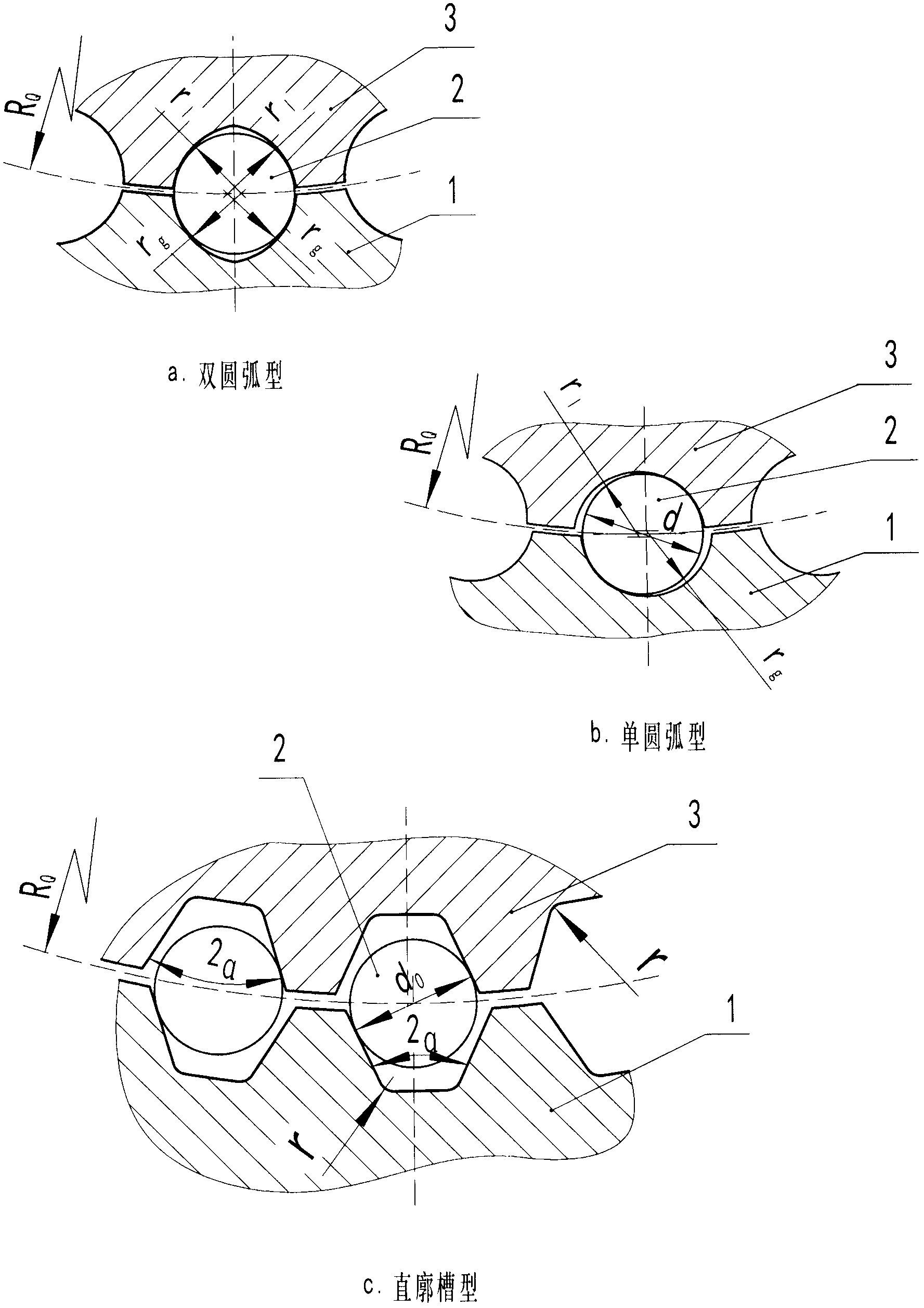
[0025]The ball worm pair proposed by the present invention has two types of envelopes (single envelope and double envelope), three types of spiral grooves and four types of steel ball circulation paths, which can be combined into dozens of different types of structures. The combined structure should be determined according to various factors such as the type of load to be transmitted, accuracy requirements, environmental conditions, and production conditions. Several typical examples are presented here to illustrate the specific structural combination of two types of envelopes, three types of spiral grooves, and four types of steel ball circulation methods proposed by the present invention, their advantages and disadvantages, and applicable occasions.

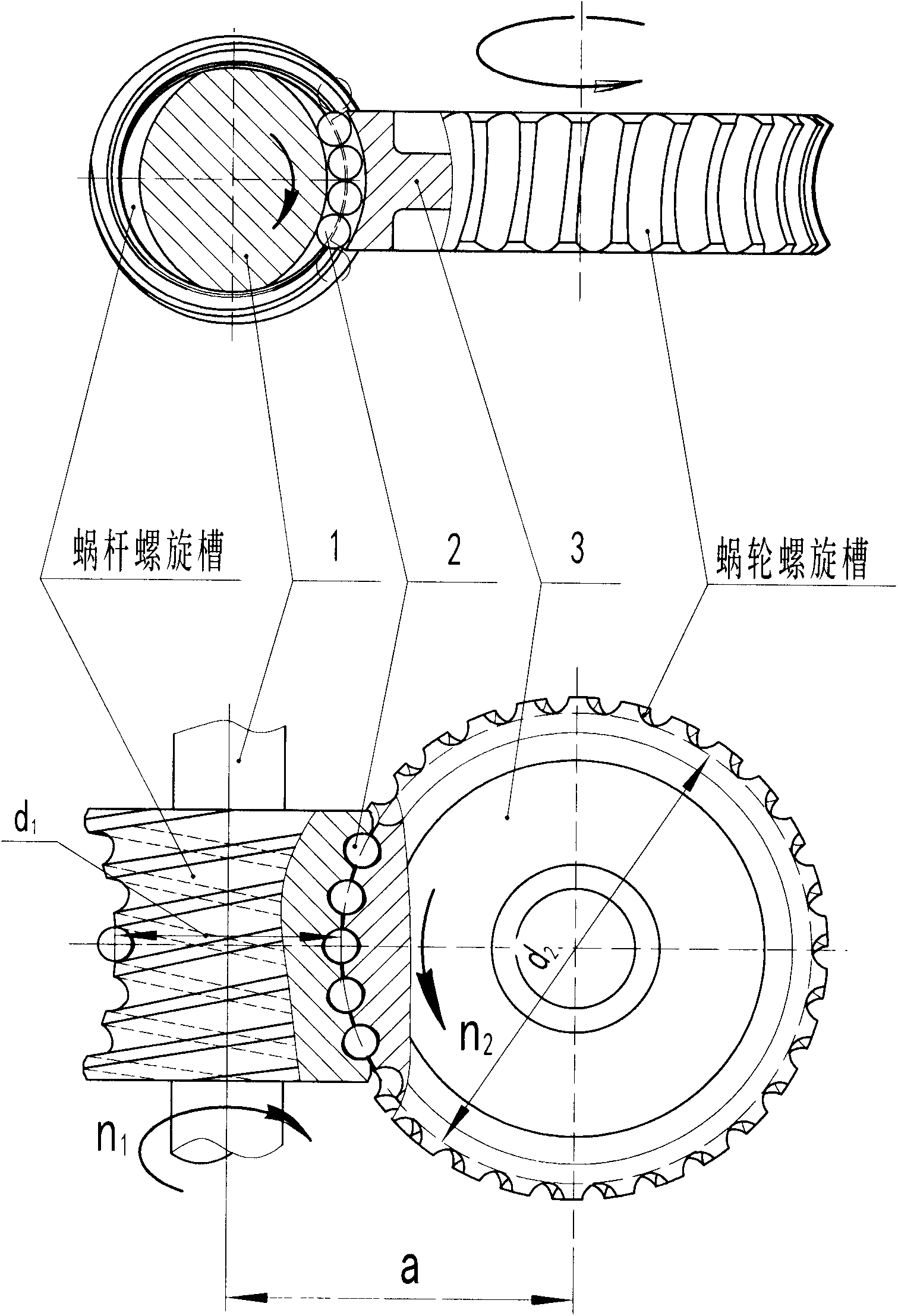
[0026] Figure 4 Shown is a double-enveloping worm pair, which adopts the implementation mode of double arc spiral grooves. The steel balls circulate through the guide tubes 5, 6 and guide holes installed at both ends of the sp...


PUM


Abstract

The invention discloses a ball worm gear pair. Steel ball rolling in a spiral groove in the outer edge of a worm and worm gear is used for replacing meshed friction movement between threaded teeth of a worm and tooth faces of a worm gear to push the worm gear to rotate, and therefore the transmission efficiency and all technological performance indexes are greatly improved. The spiral groove in the worm and worm gear can be in the shape of a single arc or double arcs or a straight outline groove by means of the normal section of the worm and worm gear or the axial section of the worm. The enveloping manner is mainly a double enveloping manner and can also be a single enveloping manner. The steel ball circulating manner includes worm inner circulation and worm gear inner circulation. A steel ball rolls in a guide piece, the spiral groove, a reverse backflow device, an inner rolling way and an outer protection cover of the worm and worm gear in a circulating mode. The ball worm gear pair is used for transmitting movement and torque between two staggered shafts in space, the speed of movement can be reduced and can also be improved, the speed reduction movement with the crossed angle sigma of the shafts being 90 degrees is mostly commonly used, and the ball worm gear pair is widely applied in mechanical transmission.

Description

technical field [0001] The invention relates to a new mechanical transmission mechanism, which is used for transmitting motion and torque between two shafts interlaced in space. The movement can be deceleration or speed-up, the most common is the deceleration movement with the shaft angle Σ=90 degrees, and the present invention will also add a new high-efficiency transmission device for the speed-up movement. Background technique [0002] At present, the worm drive known to the public is widely used in mechanical transmission. Its main features are stable transmission, low vibration, impact, and noise, compact structure, and large transmission speed ratio. The first-stage reduction transmission speed ratio is generally 5 to 70. , up to several hundred, the main disadvantage of the worm drive is the large friction loss between the worm screw teeth and the worm gear tooth surface, resulting in low efficiency, easy to generate heat, high temperature rise, and serious waste of e...

Claims


Application Information

Patent Timeline
IPC IPC(8): F16H1/16F16H55/22
CPCF16H1/163F16H55/22
Inventor 李泰安
Owner 李泰安
Why Eureka
Try Eureka