
Method and device for manufacturing light trap with hollow photonic crystal fiber

A hollow photonic crystal and optical fiber technology, which is applied in the fields of optical inertial navigation and optical engineering, can solve the problems of increasing the difficulty of alignment accuracy and capturing, affecting the effect of optical trapping force, and large laser energy loss, so as to improve energy utilization and reduce energy consumption. Influence and improve the effect of alignment accuracy

Inactive Publication Date: 2014-02-12
ZHEJIANG UNIV
View PDF2 Cites 13 Cited by
  • Summary
  • Abstract
  • Description
  • Claims
  • Application Information

AI Technical Summary

Problems solved by technology

[0004] The disadvantages of the traditional method of preparing optical fiber traps are: the spherical particles undergo Brownian motion in the liquid environment and move irregularly near the equilibrium position, which affects the effect of the optical trap force; two pairs of single-mode optical fibers are aligned with the same spherical particle or a For the single-mode fiber to align with the same spherical particle, the alignment accuracy is very strict and the capture difficulty increases; the single-mode fiber is doped with high-purity silicon core, the fiber performance and parameters such as damage threshold, attenuation, nonlinear effect and group velocity dispersion, etc. All are affected by the corresponding parameters of the silicon material. The laser energy loss emitted by the single-mode fiber is large, and the optical trap force generated by the unit optical power is small.

Method used


Image

  • Method and device for manufacturing light trap with hollow photonic crystal fiber
  • Method and device for manufacturing light trap with hollow photonic crystal fiber
  • Method and device for manufacturing light trap with hollow photonic crystal fiber

Examples


Embodiment

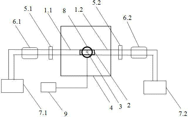
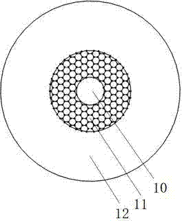
[0027] The specific steps of a device for preparing an optical trap using a hollow photonic crystal fiber are:

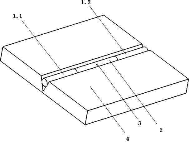
[0028] 1. Make the glass substrate 4, place the spherical particles 3 in the hollow core of the hollow photonic crystal fiber 2, fuse and connect the outgoing end faces of the two single-mode optical fibers 1 to the hollow photonic crystal fiber 2, and fix the three optical fibers by transparent ultraviolet glue In the V-shaped groove of the glass substrate 4, the schematic diagram of the glass substrate made after this step is completed is shown in the attached image 3 ;

[0029]Two, place the glass substrate 4 horizontally under the photoelectric image detector 8, open the photoelectric image detector 8, computer 9 and video acquisition software, place the microscopic objective lens of the photoelectric image detector 8 at the minimum magnification, and roughly Adjust the position of the glass substrate 4 to make the image of the hollow photonic crystal fiber 2 ...


PUM


Abstract

The invention discloses a method and device for manufacturing a light trap with a hollow photon crystal fiber. The two ends of the hollow photonic crystal fiber are connected with the emission ends of two single mode fibers in a butt fusion mode. Afterwards, fundamental mode gauss beams emitted from the two single mode fibers are used for binding globular particles in a hollow fiber core in the hollow photonic crystal fiber, and therefore the globular particles are stressed and balanced in the light trap. The gauss beams are transmitted towards each other. The light power of the different single mode fibers is changed and the light trapping force exerted on the globular particles is changed. The acceleration and the motion displacement of the globular particles are controlled. The device comprises a substrate of a fiber light trap system, the two single mode fibers, the hollow photonic crystal fiber, a coupler, a light intensity modulator, a laser device, a photoelectricity image detector, a computer and like. According to the method and device for manufacturing the light trap with the hollow photonic crystal fiber, the energy utilization rate of the laser beams and the registration precision of the laser beams are improved and the influences on the motion state of the globular particles by Brownian movement in liquid are avoided.

Description

technical field [0001] The invention relates to the fields of optical inertial navigation and optical engineering, in particular to a method and device for preparing an optical trap by using a hollow photonic crystal fiber. Background technique [0002] According to the quantum theory, a light beam is a group of photon flow with momentum moving at the speed of light. When the light beam is refracted and reflected on the surface of the medium, the speed and direction of the photon change, resulting in a transformation of its momentum vector. According to the law of conservation of momentum, the momentum transformation of the photon is equal to the momentum change of the spherical particle, so the momentum of the spherical particle changes accordingly, that is, the effect of the light beam on the existence force of the spherical particle, which is called the light radiation pressure. Included are the scattering forces along the direction of beam propagation and the gradient f...

Claims


Application Information

Patent Timeline
IPC IPC(8): G01P15/03
Inventor 贾博胡慧珠缪立军李正刚薛藩衍
Owner ZHEJIANG UNIV
Learn More