
Nickel-metal hydride battery charge-discharge circuit in uninterruptible power supply

A charge-discharge circuit, nickel-hydrogen battery technology, applied in battery circuit devices, circuit devices, current collectors, etc., can solve the problems of reducing the service life of nickel-hydrogen batteries, unable to float charge for a long time, shortening charging cycle, etc. The effect of charging frequency, high reliability and reducing operation and maintenance costs

Active Publication Date: 2013-10-23
石家庄国耀电子科技有限公司
View PDF4 Cites 4 Cited by
  • Summary
  • Abstract
  • Description
  • Claims
  • Application Information

AI Technical Summary

Problems solved by technology

The charging method of Ni-MH batteries is different from that of lead-acid batteries and lithium batteries. It cannot be floated for a long time and can only be charged by constant current.
The current constant current charger of the uninterruptible power supply will stop working after the battery is fully charged. It has been in the state of low current discharge, which shortens the charging cycle of the Ni-MH battery and increases the charging frequency, which greatly reduces the service life of the Ni-MH battery and increases the operation and maintenance costs of the uninterruptible power supply.

Method used


Image

  • Nickel-metal hydride battery charge-discharge circuit in uninterruptible power supply

Examples


Embodiment Construction

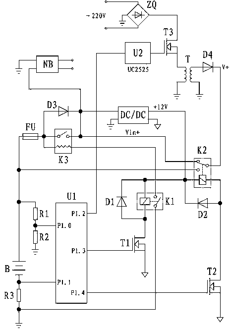
[0015] see figure 1 , the invention is composed of a charger, a discharge diode, an auxiliary power supply and a charge and discharge control circuit. The charger is composed of PWM isolation driver U2, rectifier bridge ZQ, transformer T, rectifier diode D4 and switch tube T3; the charge and discharge control circuit is composed of single-chip microcomputer U1, discharge relay K1, charge relay K2, DC contactor K3, the first freewheeling circuit The diode D1, the second freewheeling diode D2, the discharge diode D3, the discharge MOS transistor T1, the charge MOS transistor T2, the first resistor R1 to the third resistor R3 and the fuse FU are composed, and the auxiliary power supply supplies power for the charge and discharge control circuit.

[0016] The circuit works as follows:

[0017] The single-chip microcomputer U1 monitors the terminal voltage of the Ni-MH battery B through the voltage divider circuit composed of the first resistor R1 and the second resistor R2, judge...


PUM


Abstract

The invention discloses a nickel-metal hydride battery charge-discharge circuit in an uninterruptible power supply. The nickel-metal hydride battery charge-discharge circuit in the uninterruptible power supply comprises a charger, a discharge diode and a charge and discharge control circuit; the charge and discharge control circuit comprises a singlechip, a charging relay and a charging MOS (metal oxide semiconductor) tube; the charger charges a nickel-metal hydride battery through the normally open contact of the charging relay and is connected with the input end of a direct-current booster of the uninterruptible power supply through the normally closed contact of the charging relay; the control signal input end of the charger is connected with the output port of the singlechip; the charging MOS tube controls a charging relay control coil; the gate of the charging MOS tube is connected with the output port of the singlechip; the output voltage of the nickel-metal hydride battery is connected with a voltage sampling port of the singlechip after being subjected to partial pressure by a first resistor and a second resistor; a third resistor is connected in series between the cathode of the nickel-metal hydride battery and the output ground of the charger; the output signal of the third resistor is connected with a current sampling port of the singlechip; and the nickel-metal hydride battery supplies power to an inverter through the discharge diode. By the nickel-metal hydride battery charge-discharge circuit in the uninterruptible power supply, charging frequency is greatly reduced, so that the service life of the nickel-metal hydride battery is prolonged, and the operation cost and the maintenance cost of the uninterruptible power supply are reduced.

Description

technical field [0001] The invention relates to a battery charging circuit capable of preventing frequent charging and discharging of nickel-metal hydride batteries inside an uninterruptible power supply, belonging to the technical field of power supplies. Background technique [0002] Since lead-acid batteries and lithium batteries cannot be discharged at high currents at low temperatures, nickel-metal hydride batteries are generally required for uninterruptible power supplies that work in low-temperature environments. The charging method of Ni-MH batteries is different from that of lead-acid batteries and lithium batteries. It cannot be floated and charged for a long time, and can only be charged by constant current. The current constant current charger of the uninterruptible power supply will stop working after the battery is fully charged. It has been in a low current discharge state, which shortens the charging cycle of the Ni-MH battery and increases the charging freq...

Claims


Application Information

Patent Timeline
IPC IPC(8): H02J7/00
Inventor 董银虎管恩怀赵书伟路瑜亮王京民郭玺王大海葛鹏郝晓阳孟宪高
Owner 石家庄国耀电子科技有限公司
Learn More